54 Installation Manual
Inverter / CTs
• The CTs must be placed around the correct wire. They are labeled
CT1 to connect to L1 and CT2 to connect to L2.
• The CTs must face the correct direction. The "House(K)" side of the
CT must face the main panel and the "Grid(L)" side must face the
meter.
• CT cable is 10m as default.
• CT cable can be extended to maximum of 30m, contact support@
electriqpower.com for additional support.
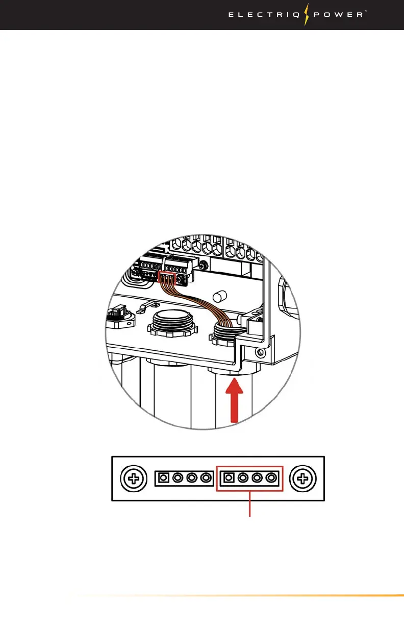
3. Route the other end of the CT through the CT port and insert the
4-Pin terminal at the inverter as shown below.
4. After all the wiring connected, close the wiring distribution box,
ensure waterproof and moisture-proof and sealed well.
CT Connection