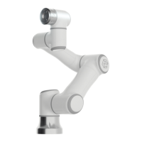
Figure 6-2 Schematic diagram of workspace of the robot
6.4 Robot Installation
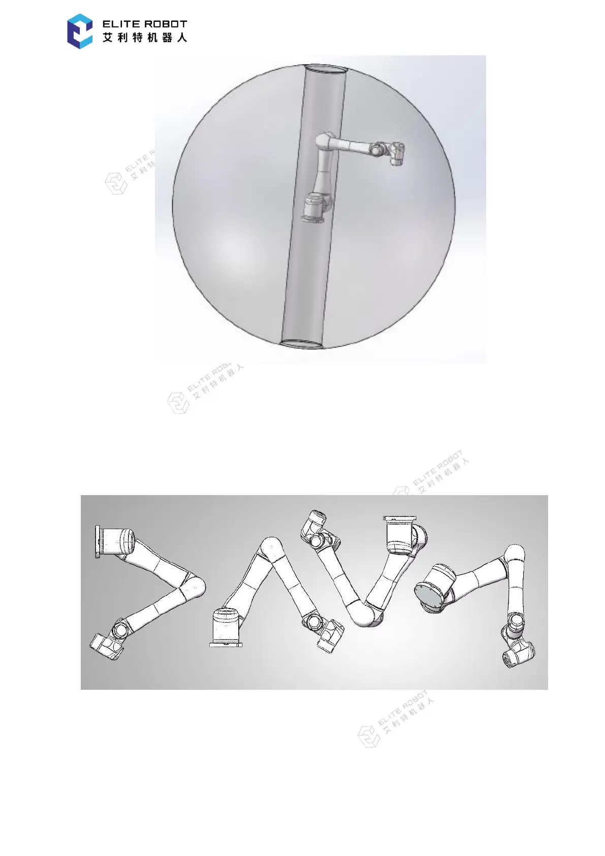
The robot has the 360° pose self-adaptive function at the installation location, and is compatible
with installation, hoisting, wall mounting and other specific installation ways on the base, as shown
in Figure 6-3.
Figure 6-3 Schematic diagram of different installation poses
When installing on the base, the robot body is fixed on the base with four M6 bolts. It is
recommended to install the pins with two holes, as to improve the installation accuracy. The
mechanical dimensions are shown in Figure 6-4.