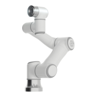
6.5 Installation of the End/Tool Effector
The tool flange has four M6 threaded holes and one Ф6 positioning hole, in this way the clamp
may be conveniently installed and connected to the robot end. The mechanical dimensions of the tool
flange are shown in Figure 6-5.
Figure 6-5 Mechanical dimensions diagram of the tool flange of the robot, with unit of mm
1. Make sure the tool is correctly and securely installed in place.
2. Make sure the tool is safely constructed such that it cannot create a hazardous situation by a
dropping part unexpectedly.
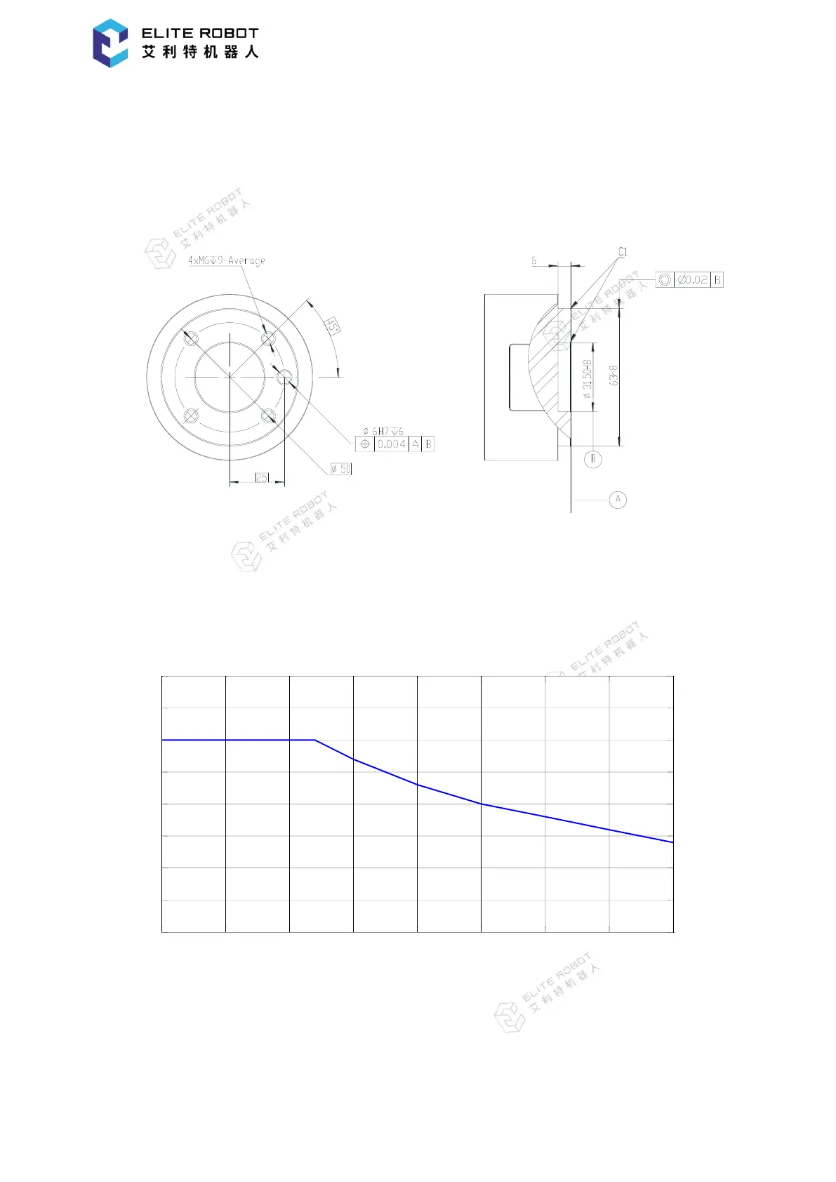
Figure 6-6 payload diagram
A wrist payload diagram is shown above. Herein, the horizontal ordinates D respectively
indicates the offset of the center of gravity. The offset of the center of gravity is the distance from the
center of the flange plate of the tool/end effector to the center of gravity of the tool.