Display Operation Manual BC2000 and JC2000 Controller ~ Doc. No. 2055882, Issue 5.1, June 2014 7
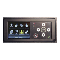
Status Indicators
The display unit has green (OK) and red (ALM) LEDs. The green LED is always ON
when the controller is powered, unless a system alarm is present. When a system
alarm is present the red LED turns ON.
Navigation Buttons
The display has one scroll knob and two buttons for navigating controller menus:
◄ (Left Button) is used to go back or abort
► (Right Button) is used to go forward or apply
(Scroll Knob) is used to scroll up or down in the menus or change the values
NOTE: All scroll knob directions in this document assume a clockwise turn, which
scrolls downward through pages and menus, and increments numerical values.
Audible Alarm
The display unit has an audible alarm located in the rear. When an audible alarm is
present, press left or right button to silence the alarm sound.
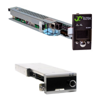
Controller Connections
The controller has the following connections:
1. CAN – Communicates with external Eltek Peripheral Monitoring Device
PM86001 or PM86000.
2. LAN – Accepts an Ethernet cable for browser-based interface (see
DOCUMENT)
3. I
2
C – Communication connection to external Eltek distributions
4. Temp/Aux – Input ports that accept temperature probes and/or dry-contact
relays
5. Alarm Relay – Form-C output alarm relays (requires Eltek cable, sold
separately)
6. Display – Connection for the controller display