8 Display Operation Manual BC2000 and JC2000 Controller ~ Doc. No. 2055882, Issue 5.1, June 2014
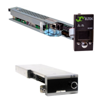
Figure 2 - BC2000 Controller Connections
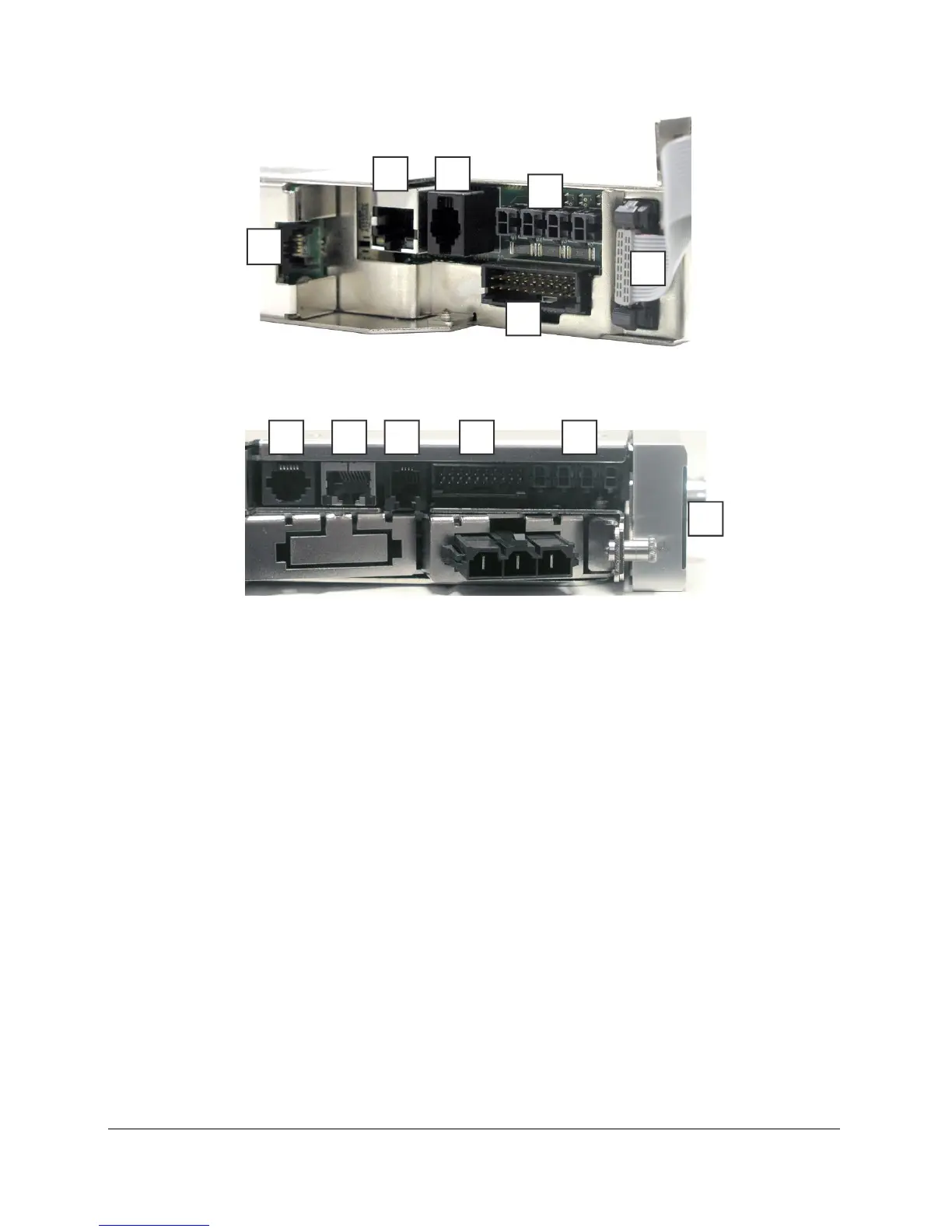
Figure 3 - Controller Connections (JC2000)
CAN Bus
The controller is equipped with one Controller Area Network (CAN) bus port for
connecting peripheral monitors (PM). PM devices provide additional alarm I/O to the
BC2000. The controller can support up to 8 daisy-chained devices. For more
information, consult the PM86001 Peripheral Monitor Installation Guide, Doc. No.
370015.033.
Alarm Cable Connection
Six form C alarm relays are provided through a connector labeled “Alarm Relay” (see
Figure 2). To access these alarms, use the cable assembly (sold separately) that
has the mating 20-pin Molex connector on one end and bare tinned wire on the
other. Available alarm cable part numbers are CA210203104 (10ft), CA210203105
(50ft), and CA210203106 (100ft). Plug the cable connector into the “Alarm Relay”
connector on the controller. As for the end with bare wire, there are three wires for
each relay providing both normally open (NO) and normally closed (NC) alarm
functionality. See Table 2 for the color code for each alarm channel (relay). Select
the proper alarm type and connect the cables to the alarming equipment.
2 3
4
5
6
1
3 2 1 4
6
5