Display Operation Manual BC2000 and JC2000 Controller ~ Doc. No. 2055882, Issue 5.1, June 2014 9
NOTE: The alarm names in Table 2 are based on the default controller with profile
number 01 (e.g., 1A01-10VC). Refer to the instructions for determining the
controller’s profile number in the section “Profile and Preset” on page 16 to
determine the controller’s profile number. A relay test can be used to verify that
the alarm cable is connected properly. See details on page 24.
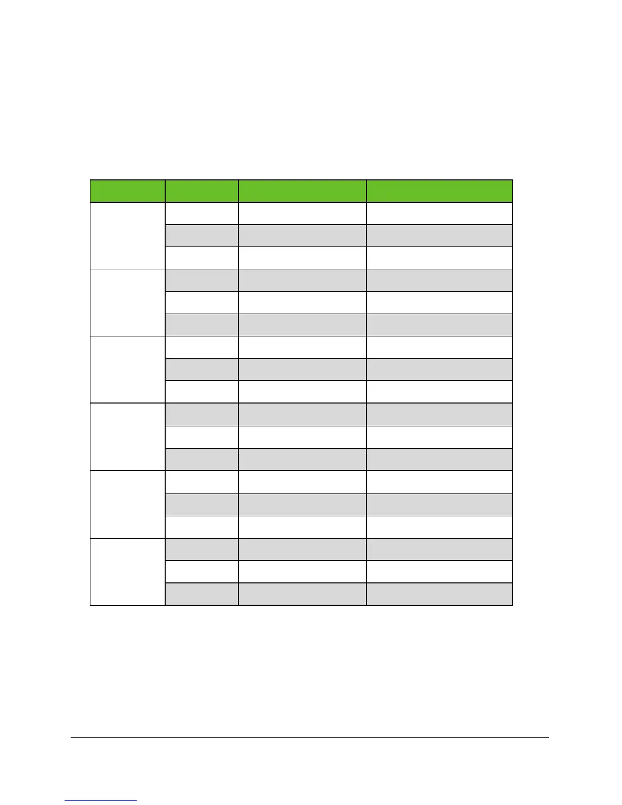
Table 2- Alarm Cable Color Code
Alarm Relay Designation Wire Color Description
A
NC Orange/White Stripe Contact Opens on Alarm
C Orange Common
NO Orange/Black Stripe Contact Closes on Alarm
B
NC Red/White Stripe Contact Opens on Alarm
C Red Common
NO Red/Black Stripe Contact Closes on Alarm
C
NC Green/White Stripe Contact Opens on Alarm
C Green Common
NO Green/Black Stripe Contact Closes on Alarm
D
NC Yellow/Stripe Contact Opens on Alarm
C Yellow Common
NO Yellow/Black Stripe Contact Closes on Alarm
E
NC Light Blue/White Stripe Contact Opens on Alarm
C Light Blue Common
NO Light Blue/Black Stripe Contact Closes on Alarm
F
NC Tan/White Stripe Contact Opens on Alarm
NO Tan Common
NC Tan/Black Stripe Contact Closes on Alarm
Alarms can be mapped to the output relays. The default relay map is shown in Table
3 on page 31. These relays can be customized through the web interface. For
additional details on mapping alarms, refer to the Web Interface Manual
BC2000/JC2000 Controller, Doc. No. 2056625.