Operating the machine
7
1.2 Mechanical connection to the analyzer
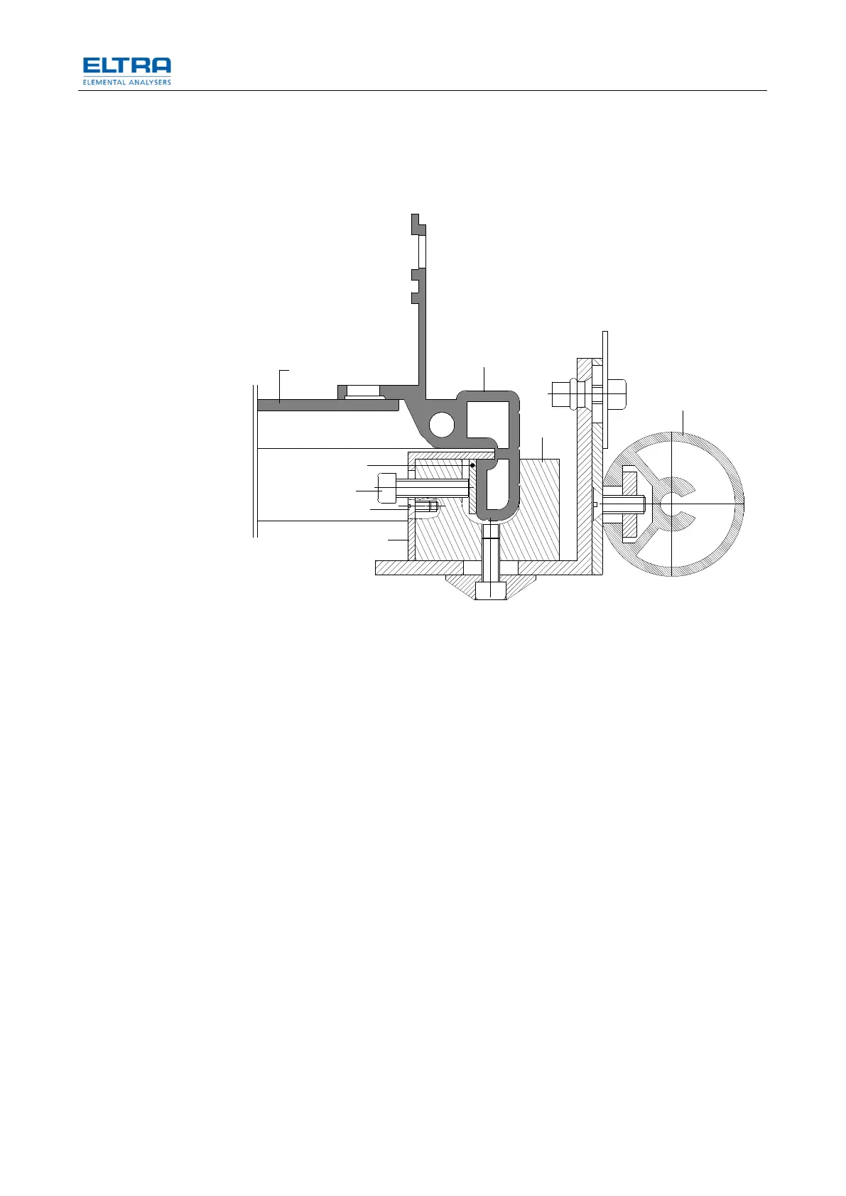
Fig. 4: Autoloader reinstallation (Top view)
• Before starting reinstallation take a look at the plastic tubes and bear in mind
the way they are supported with the screw (7). Make sure to lay them the
same way during reinstallation.
• Place the loader to the right of the analyzer. The part (1) is the vertical bar
(profile) of the front right corner of the analyzer’s cabinet (top view of cross
section). For further orientation: The round part (2) is the left front foot of the
loader.
• The loader is positioned in a way that the vertical rod (3) is pushed towards
the cabinet so that the cabinet’s corner rod (1) is inside the vertical rod (3).
• The blade (4) is inserted between the rod (3) and the cabinet rod (1).
• The angle rod (5) is installed and fixed with the screws (6).
• Then the screws (7) are fixed so that a solid, stable mechanical connection
between analyzer and loader is made.