56 789101112
1234
M
M
13 14 15 16 17 18 19
COM
APCH
APED
COM
STOP
FOTO
STPA
17
System set-up
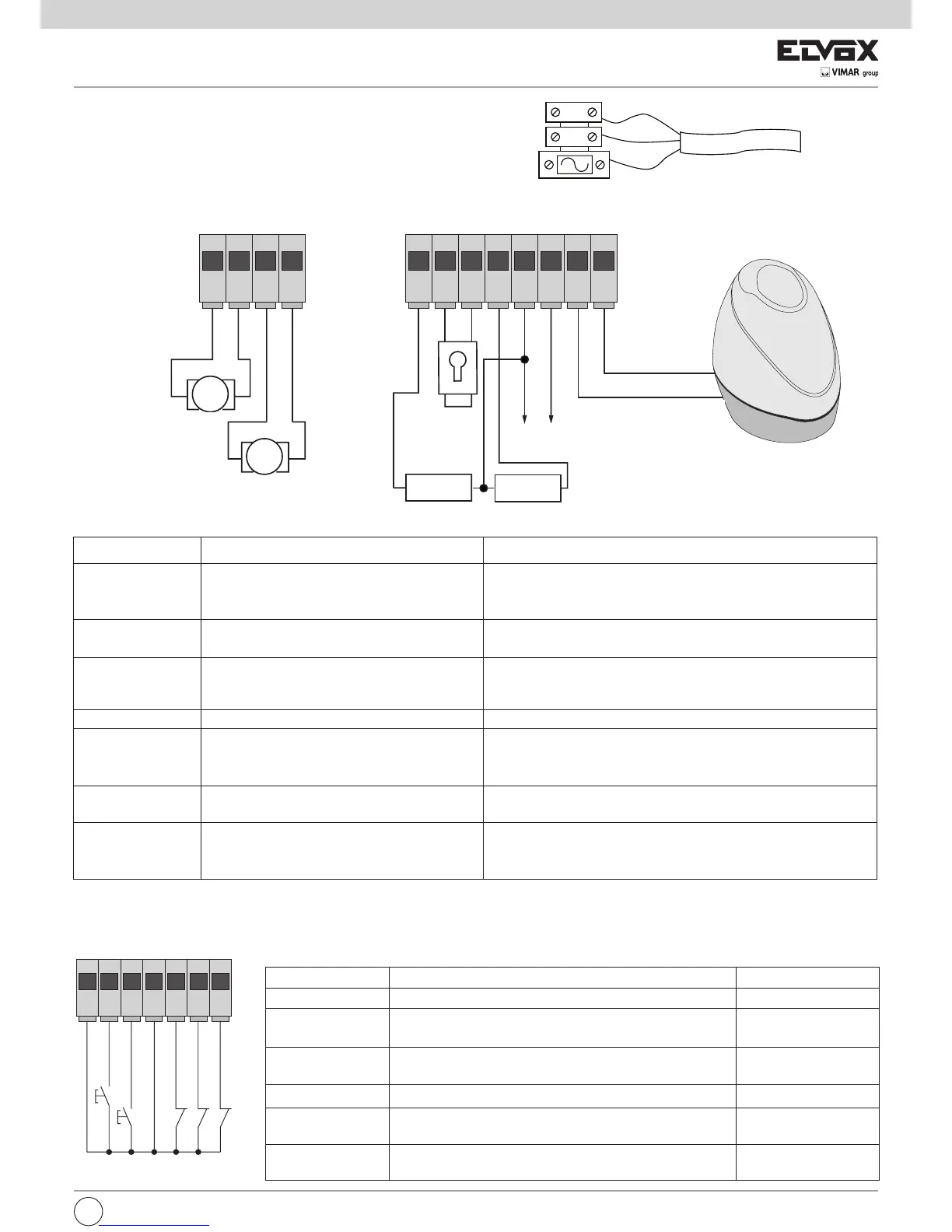
4.1- Power supply line wiring
Inside the transformer compartment there is a terminal with a 2 A pro-
tection fuse, connect the phase in the corresponding pole to the fuse.
4.2- Wiring for flashing light, courtesy light and gate movement warning light
24 Vdc 15 W max
24 Vdc 120 mA max
Courtesy light or second radio channel
24 Vdc 120mA max
gate movement warning light
Accessories power supply output
24 Vdc 300mA max
-
+
-
-
-
+
Electrical lock
12 V 15 VA
Fig. 5
4.3- Input connections:
The control unit is supplied with jumpered normally closed inputs (STOP, FOTO AND STPA) remove the jumper from the input you are going to use.
Terminal number Description Function
1-2 Output for powering the electric motor 1
(pedestrian)
Output for controlling electric motor 1 at 24 Vdc rated power 50 W (1
opening, 2 closing)
3-4 Output for powering the electric motor 2 Output for controlling electric motor 2 at 24 Vdc rated power 50 W (3
opening, 4 closing)
5-9 Courtesy light or second radio channel Output 24 Vdc maximum load 120 mA, can be programmed as a timed
output (100 seconds) or second radio channel output, see dip switch
number 6 (5= GND, 2can/ 9= + 24 Vdc).
6-7 Output for electrical lock control Output for electrical lock at 12 Vac maximum 15 VA
8-9 Gate movement warning output Gate movement warning output, flashes slowly when opening, on steady
with gate open, flashes quickly during closing and off with gate closed (8 =
controlled GND, 9 = permanent + 24 Vdc, maximum load 120 mA)
9-10 Accessories power supply output Output 24 Vdc maximum 300 mA for supplying the photocells and
accessories (9 = + 24 Vdc, 10= GND)
11-12 Output for flashing light Output 24 Vdc maximum load 15 W for flashing light (11 = GND flashing
light, 12 = + 24 Vdc) , if the automatic closing function is active the flashing
light stays on steady during the automatic closing time.
Terminal number Description Input type
13-16 Control inputs common (permanent GND) _
14
Sequential control input, for controlling the complete travel of the
gate
Normally open
15
Sequential control input, for controlling the pedestrian travel of
the gate
Normally open
17 Input for stopping the gate Normally closed
18 Photocell input, active during gate closing Normally closed
19
Input for edges or internal photocell, active during gate closing
and opening
Normally closed
Motor 1 Pedestrian
Motor 2
The sum of the absorptions of the 2CAN, AUX and -VA outputs must not exceed 500mA.
EN
Mains
Transformer
Neutral
Phase


 To Next Page
 Loading...