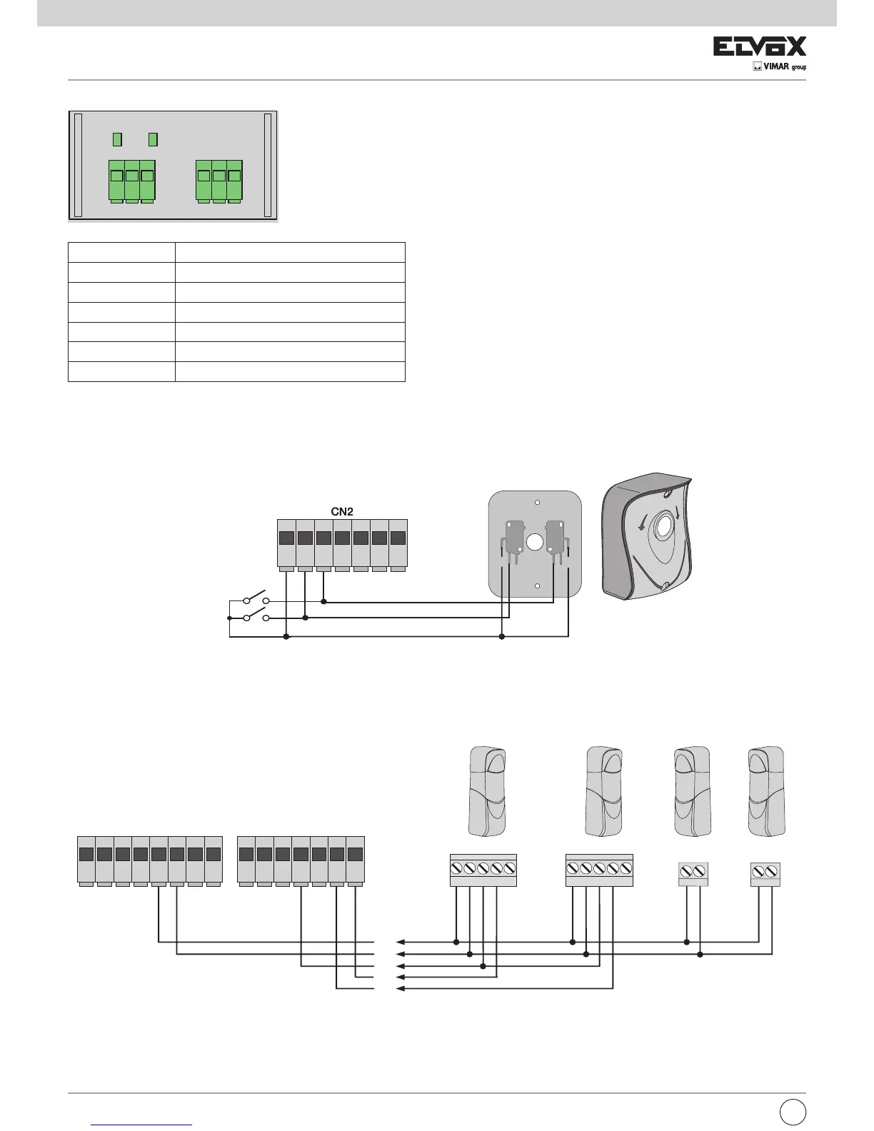
4.4- Collegamento pulsanti di comando e selettore a chiave
Contatti normalmente aperti (i LED rossi AP/CH o APED si accendono quando viene azionato il selettore o i pulsanti collegati in parallelo):
4.5- Collegamento fotocellule
Contatto normalmente chiuso (a fotocellule non impegnate il LED FOTO e il LED STPA devono essere accesi), se non utilizzato fare un ponticello tra
COM. e FOTO e STPA, è necessario rispettare la polarità per l’alimentazione delle fotocellule:
4
Fig. 6
Fig. 7
Collegamento encoder
Numero morsetto Descrizione
22 Ingresso segnale encoder motore 1
23 Negativo alimentazione encoder motore 1
24 Positivo alimentazione encoder motore 1
25 Ingresso segnale encoder motore 2
26 Negativo alimentazione encoder motore 2
27 Positivo alimentazione encoder motore 2
Scheda interfaccia encoder
I
COM COM
N.O. N.O.N.C. N.C.
13 14 15 16 17 18 19
RX1
+-CNCN