EMC INDUSTRIAL GROUP LTD Connections
MW61A_IM_ALL_SV6.09d_en 11/47
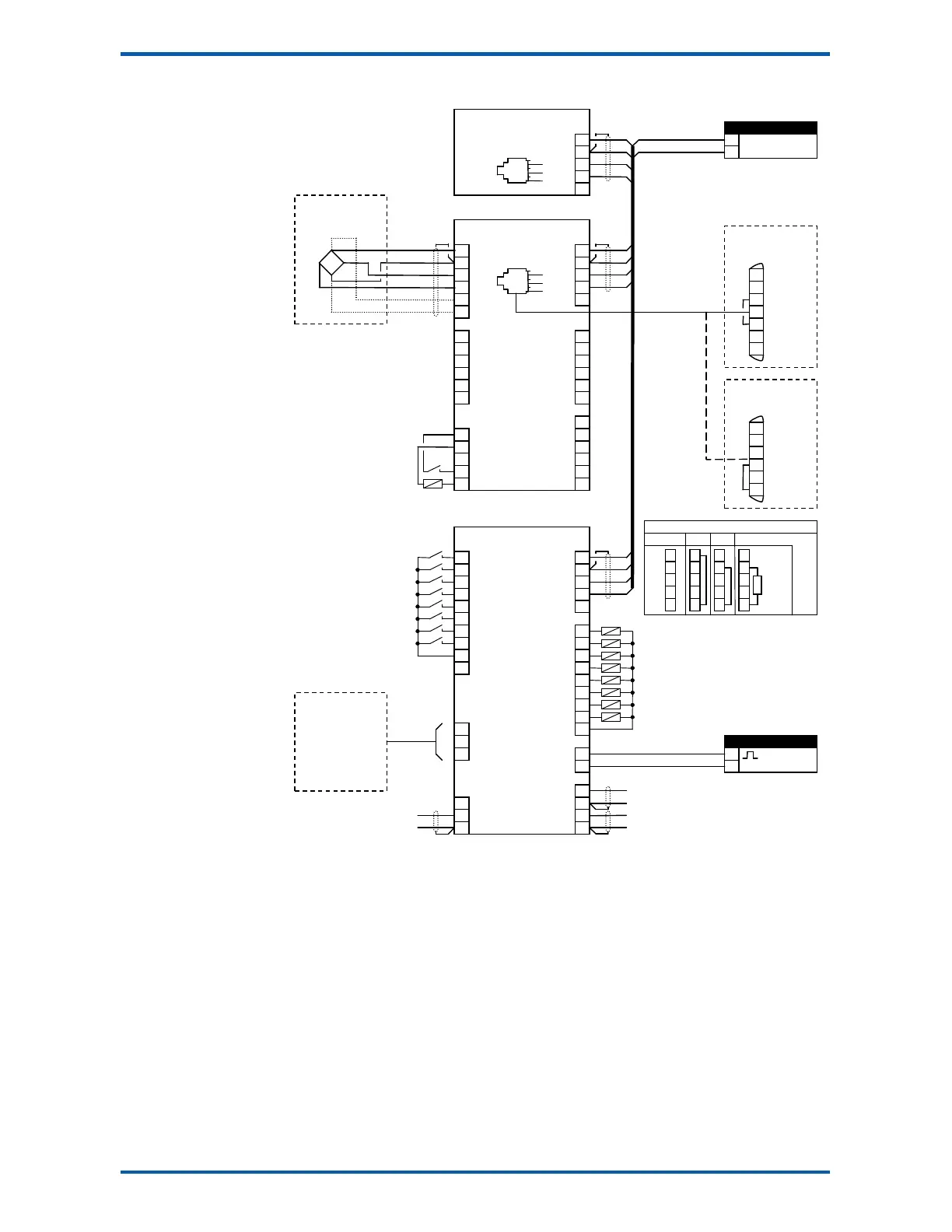
Connection Diagram – MT1
limit 1 output
limit 2 output
motion
healthy
net mode
at zero
weight fault
alarm alert
L1
7
8
6
7
20
DB9F
DB25M
PC, PLC
or
ModWeigh Display
MD1,MD2
gross weight
weight
acquire zero
acquire tare
print
capture weight
print total
reset total
totalise
hold flowrate
optional sense for 6 wire
connection
1
1
1
1
2k2
4k7
10k
22k
47k
100k
5
6
7
8
9
10
J1
J2
R1
R2
R3
R4
R5
S4
S5
S6
acquire zero
limit 2 output
Keep all wiring separated
from mains wiring.
Use shielded cable where
indicated.
For individual loadcell sensi-
tivity adjustment, use termi-
nals P, Q, R and S.
Display and transmitter can
alternatively be connected
COM1 to COM1 using an MAC
cable.
MT1 bus address set with
ADS pin or a setting.
MR1 bus address set with
ADS pin and must be same
as MT1.
Fit an MAT terminator to
each end of COM2 cable if
length exceeds 50m.