EMC INDUSTRIAL GROUP LTD Connections
MW61A_IM_ALL_SV6.09d_en 12/47
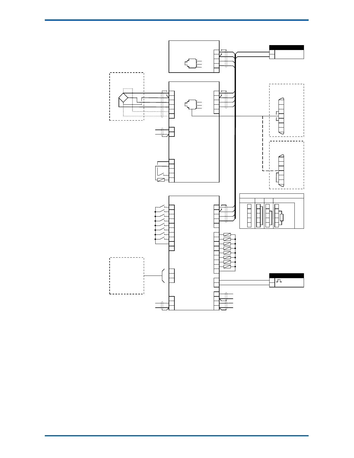
Connection Diagram – MT3
Loadcell Connections
The loadcell(s) may be wired directly to the loadcell terminals or connected together in the field with a
junction box and connected to the ModWeigh unit with a single cable.
When connected to the terminals only a 4-wire connection is used, and digital corner adjustments are
possible. (MT1 only)
When connected with one cable and a junction box no corner adjustments are possible. It is preferable
to use a 6-wire connection as this eliminates voltage drop errors in long cables caused by cable resis-
tance.
limit 1 output
limit 2 output
motion
healthy
net mode
at zero
weight fault
alarm alert
L1
7
8
6
7
20
DB9F
DB25M
PC, PLC
or
ModWeigh Display
MD1,MD2
gross weight
weight
acquire zero
acquire tare
print
capture weight
print total
reset total
totalise
hold flowrate
optional sense for 6 wire
connection
1
1
1
1
2k2
4k7
10k
22k
47k
100k
5
6
7
8
9
10
J1
J2
acquire zero
limit 2 output
Keep all wiring separated
from mains wiring.
Use shielded cable where
indicated.
Display and transmitter can
alternatively be connected
COM1 to COM1 using an MAC
cable.
MT3 bus address set with
ADS pin or a setting.
MR1 bus address set with
ADS pin and must be same
as MT3.
Fit an MAT terminator to
each end of COM2 cable if
length exceeds 50m.