EMC INDUSTRIAL GROUP LTD Connections
MW61A_IM_ALL_SV6.09d_en 9/47
The display is normally located to suit an operator. The transmitter can be located in the field to reduce
field wiring or can be located with the display for a more conventional approach.
The I/O can conveniently be situated on a DIN rail in a cabinet.
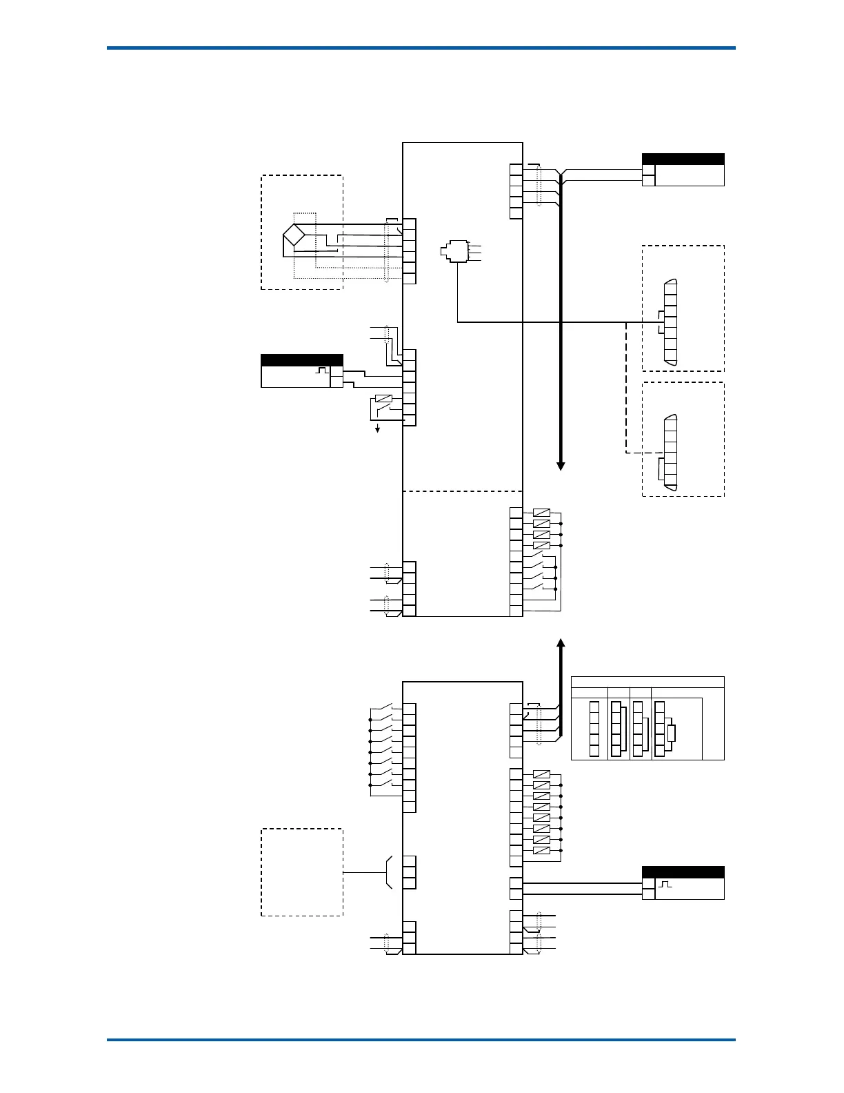
Connection Diagram – MP2
limit 1 output
limit 2 output
motion
healthy
acquire zero
acquire tare
print
capture weight
2
3
2
DB25M
weight
optional sense for 6 wire
connection
A1
A2
limit 2 output
acquire zero
limit 1 output
limit 2 output
motion
healthy
net mode
at zero
weight fault
alarm alert
PC, PLC
or
ModWeigh Display
MD1,MD2
gross weight
weight
acquire zero
acquire tare
print
capture weight
print total
reset total
totalise
hold flowrate
A3
DB9F
3
4
5
3
4
5
3
4
5
3
4
5
2k2
4k7
10k
22k
47k
100k
5
6
7
8
9
10
Keep all wiring separated
from mains wiring
Use shielded cable where
indicated