EMC INDUSTRIAL GROUP LTD Setup
MW61A_IM_ALL_SV6.09d_en 14/47
Setting the COM1 Modbus Address
Before a multidrop system will operate, the addresses in each of the ModWeigh units will need to be set
differently. This can be done by wiring a link or resistor to the ADS terminal where available. See the
table on the connection diagram. Alternatively the address setting can be changed in each unit using a
display connected to its COM1.
The following procedure is used to set a units address.
1. Press the Q key to access the setup menu.
2. Key in the quick key code 2512 to select the ‘COM1&2 modbus address’ step.
3. Press the EDIT key. (If editing is locked, key in the password 111 and press ENTER).
4. Enter the desired address (1, 2 or 3 etc.) and press ENTER.
5. Press and hold the BACK key to return to normal operation.
6. Repeat for each of the units which are to be used on the bus.
When the multidrop system is then connected and powered, the display should be able to see each of
the ModWeigh systems. This is done by pressing the SELECT key on the display.
SETTING UP
Setup
ModWeigh instruments must be calibrated for each specific application. The parameters stored are col-
lectively known as the Setup.
Description
Press the Q key to access the setup menu.
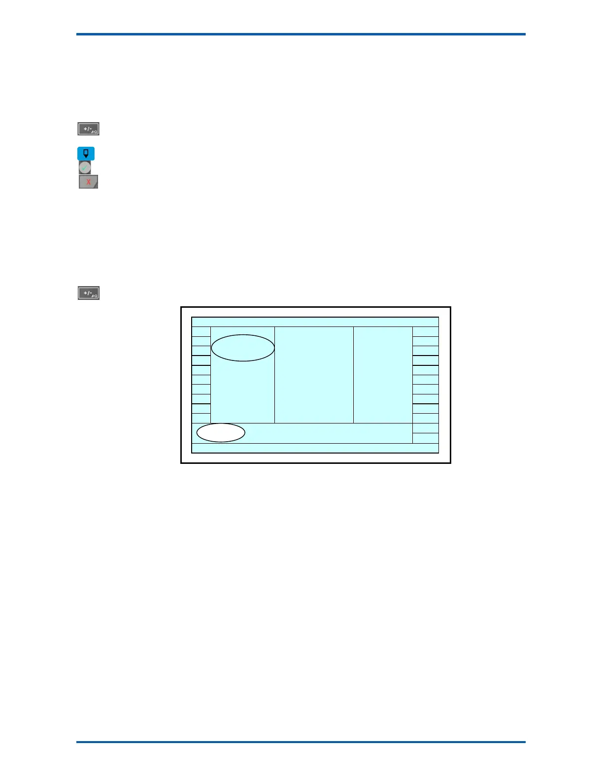
The setup is divided into sections as shown in the following diagram.
SETUP
Basic Settings
AI1 AO1
AI2 AO2
IN1 OUT1
IN2 OUT2
IN3 OUT3
IN4 OUT4
IN5 OUT5
IN6 OUT6
IN7 OUT7
IN8
Inputs
Internal Signals
Outputs
OUT8
COM1
Communications & Display
COM2
Information, Resets & Final Calibration
Setup Diagram
The Setup contains
Settings
and
Macros
which are described next.
Settings
Most of the setup for a system involves setting calibration constants which for example calibrate the
loadcell input, the 4-20mA outputs and the operation of relays etc. These settings are simple numeric
values.
Macros
Macros are used to store short programs which are used to construct text strings to output to the
printer, perform arithmetic calculations and other special control functions. Macros are a collection of
program segments which can call one another as subroutines. They have structured if/then/else state-
ments and program looping constructs.
A macro is a sequence of numbers (bytes with values of 0 to 255).
Menus
All the setup parameters are contained within a menu structure which follows the setup sections.
Basic Settings
Inputs
Internal Signals
Outputs
Communications & Display
Information, Resets & Final Calibration
Factory Settings
Loadcell
Calibration