EMC INDUSTRIAL GROUP LTD Display
MW61A_IM_ALL_SV6.09d_en 43/47
Input Functions (level sensitive Π or edge sensitive )
160 0
161 1
162 2
163 3
164 4
165 5
166 6
167 7
168 8
169 9
170 10
171 11
172 12
173 13
174 14
175 15
Control4
Modbus Access
The communications ports of the ModWeigh Controllers (COM1 and COM2) use Modbus protocol. This
can be used to access any data value and any user setting.
The Modbus protocol supported is RTU. (ASCII mode is not supported). Transmission is with 8 data bits,
no parity and 2 stop bits. The following function codes are supported;
3 - read holding registers
4 - read input registers
6 - preset single register
16 - preset multiple registers (10 hex)
23 - read/write multiple registers (17 hex)
Data can be accessed as floats (4 bytes) or integers (2 or 4 bytes). Floats are preferred as the data is
stored in engineering units. The following table shows how the addresses shown in the setup summary
are translated into Modbus register addresses. (Note with Modbus protocol, the actual address transmit-
ted is one less than the register address. With some systems, you must specify an address one less
than expected).
Address Modbus Register Address Data description
1000 to 4999 Address 1000 to 4999 Macro strings
8000 to 8999 6000 + (Address - 8000) / 2 6000 to 6499 Integer (16 bit) (limited by integer range)
8000 to 8999 7000 + (Address - 8000) 7000 to 7999 Long integers (32 bit words)
8000 to 8999 Address 8000 to 8999 Float (IEEE 4 byte reals)
The interface registers starting at address 8000 contain the most common data required for Modbus ac-
cess.
Modbus registers are 2 bytes, so 4 byte floats or 4 byte integers are stored in two consecutive registers.
The following tables provide information for Modbus access to the transmitter.
Address Data description
1000 to 4999 Macro strings (contains printouts and programs)
8000 to 8029 Interface registers (PLC access)
8030 to 8699 Configuration settings (full instrument calibration)
8700 to 8899 Data outputs (values produced by the instrument)
8900 to 8999 Activations (when set, a process is activated e.g. a zero or span)
Control and status bits can be read over modbus. Refer to the IO Function table page 40 and the Inter-
face Registers page 33 for further information.
Bits may be set in one of two ways. Either by writing to the control registers (contol1C, control1G, con-
trol2, control3) or by setting and resetting individual bits using the “IO Control” register.
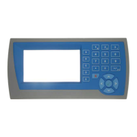
OPERATION
The display normally shows the detailed operating status of the system. There are 5 soft keys with la-
belled functions. Dedicated keys give access to the operator menu, alarm menu, system select menu,
setup menu and change the displayed data.
Display
Following is a description of the various elements of the display.