7
Reference Manual
00809-0200-4420, Rev HC
Section 2: Configuration
July 2015
Configuration
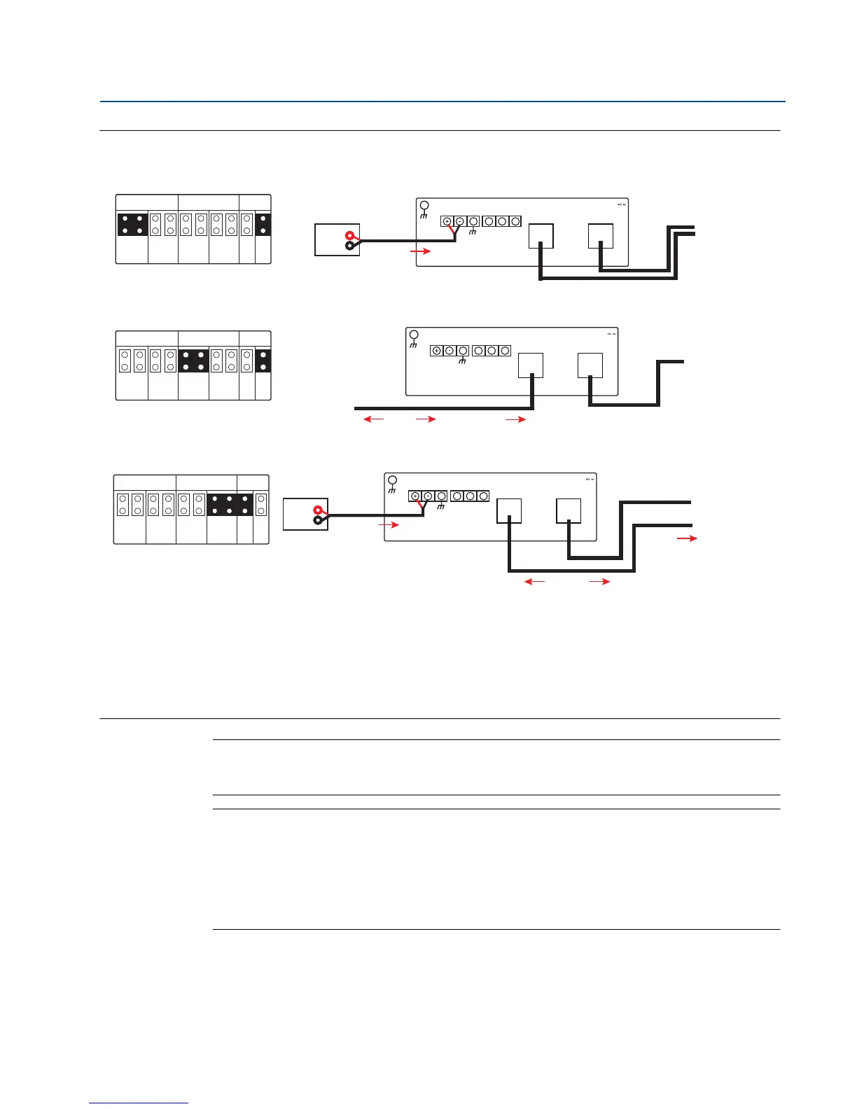
Figure 2-3. 1420 PoE Jumpering
Legend:
ETH1: Ethernet port 1 selected for PD or PSE
ETH2: Ethernet port 2 selected for PD or PSE
PD: Gateway derives power from the Ethernet port selected
PSE: Gateway derives power from a local power supply and sends power down the Ethernet port selected to another device
EN: Enabled; this enables the PSE operation
DIS: Disabled; this disables the PSE operation
Note
Only one port and one mode of operation (PD or PSE) can be selected at a time; any other
combination of jumpers is invalid.
Note
IEEE 802.3af-2003 PoE standard provides up to 15.4 W of DC power (minimum 44 V DC and 350
mA) to each device. Only 12.95 W is assured to be available at the powered device as some
power is dissipated in the cable.
IEEE 802.3at-2009 PoE standard also known as “PoE+” or “PoE plus”, provides up to 25.5 W of
power. The 2009 standard prohibits a powered device from using all four pairs for power.
For more information on PoE and frequently asked questions, reference document number
00870-0500-4420 or Section 3.4.6.
In order to use both ports for PoE, remember to order option code “2” when selecting number
of Ethernet ports.
Traditionally Powered Gateway
PoE, Gateway as a PD via Ethernet Port 2
PoE, Gateway as a PSE via Ethernet Port 2
PD PDPSE
ETH1 ETH2 PSE
PSE
EN
DIS
S
A
B
Case
Ethernet 2 Ethernet 1
To Host
Power
Modbus10.5V-30V
Input Power
S
A
B
Modbus10.5V-30V
Input Power
Case
Ethernet 2 Ethernet 1
From PSE Device
Power
PD PDPSE
ETH1 ETH2 PSE
PSE
EN
DIS
To Host
Data
PD PDPSE
ETH1 ETH2 PSE
PSE
EN
DIS
Power
S
A
B
Case
Ethernet 2 Ethernet 1
To Host
To POE Device
Power
Modbus10.5V-30V
Input Power
Data
 Loading...


