Installation, Operation and Maintenance Manual
MDE 257 Rev. 1
February 2022
39
Section 8: Connector Base Card
Connector Base Card
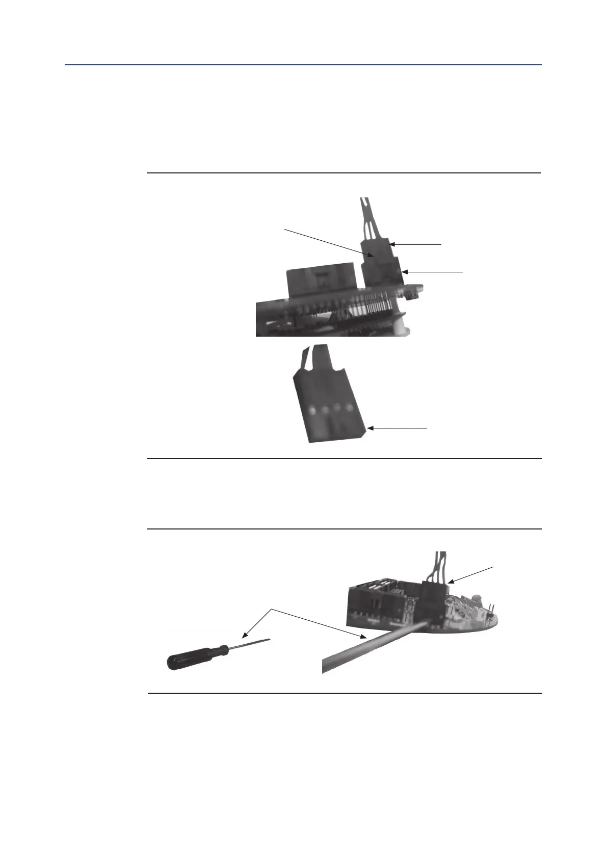
The connector is composed of two pieces: header and crimp housing. The header is welded to
the printed circuit board and the crimp housing is connected to wires. The mechanical block
(see Figure 11) part of the crimp housing can complicate the disconnection of the crimp housing
from the header, which if done without due care can potentially result in damage to the connector
and/or wires.
Figure 11
Header
Crimp housing
Mechanical block
Crimp housing
mechanical block
Direction to force
the mechanical block
Screwdriver
Disconnection of the header and crimp housing can be facilitated with a screwdriver. Use the
screwdriver to force the mechanical block in the direction indicated in Figure 12 below until the
crimp housing becomes free from the header.
Figure 12

 Loading...


