Mode options
• Open Collector (requires external excitation supply voltage and pull-up resistor)
• TTL (internally powered by the meter 0-5 VDC signal)
Channel B Phase options
• Lag forward, Lead reverse (Phase B lags Phase A while reporting forward flow, leads
Phase A while reporting reverse flow)
• Lead forward, Lag reverse (Phase B leads Phase A while reporting forward flow, lags
Phase A while reporting reverse flow)
Phase A and Phase B output (based on flow direction)
• Reverse flow - output only reports flow in the reverse direction. For frequency
outputs, Phase B of the output is 90 degrees out of phase with Phase A.
• Forward flow - output only reports flow in the forward direction. For frequency
outputs, Phase B of the output is 90 degrees out of phase with Phase A.
• Absolute - output reports flow in both directions. For frequency outputs, Phase B of
the output is 90 degrees out of phase with Phase A.
• Bidirectional - output reports flow on Phase A only in the forward direction and on
Phase B only in the reverse direction.
Maximum frequency for the frequency outputs
• 1000Hz
• 5000Hz
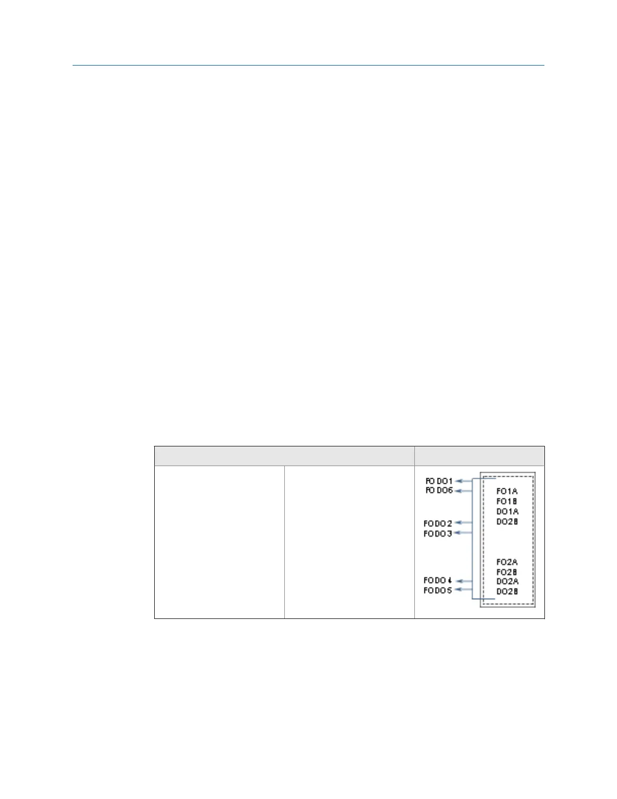
Frequency/Digital output
Source configuration
Frequency /Digital Output 1
Frequency /Digital Output 2
Frequency /Digital Output 3
Frequency /Digital Output4
Frequency /Digital Output 5
Frequency /Digital Output 6
• Frequency output 1A
• Frequency output 1B
• Digital output 1A
• Digital output 1B
• Frequency output 2A
• Frequency output 2B
• Digital output 2A
• Digital output 2B
Output for FODO1 and Digital Input 1 or FODO6 (Type 4 CPU) (Group 1 on the CPU
Module) share a common ground and have 50V isolation. FODO2, FODO3, FODO4 (Type 4
CPU), and FODO5 (Type 4 CPU) (Group 2 on the CPU Module) share a common ground and
have 50V isolation. This allows an output to be connected to a different flow computer.
The outputs are opto-isolated from the CPU Module and have a withstand voltage of at
least 500V rms dielectric.
Electrical installation
74 Gas Ultrasonic Flow Meter

 Loading...


