6. Remove the three Acquisition Module flat head screws and split lock washers, then
remove the Acquisition Module from the Base Enclosure.
7. Insert the new Acquisition Module into the Base Enclosure and secure with the three
split lock washers and flat head screws.
8. Reattach the terminal blocks onto the Acquisition Module (3 mm flat head screw
driver required). Make sure the transducer wires have good contact with the
terminal block and the terminal block screws are tight.
9. When you have completed attaching the Transducer wire terminal blocks and the
Acquisition cable terminal block to the Acquisition Module, check the Base
Enclosure o-ring and reinstall if necessary.
10. Reattach the Transmitter Electronics Enclosure to the Base Enclosure with the four
hex head bolts and lock washers. Tighten bolts with a 6 mm Allen wrench.
11. Retighten or reattach the conduit to the Transmitter Electronics Enclosure using a
crescent wrench or channel lock pliers.
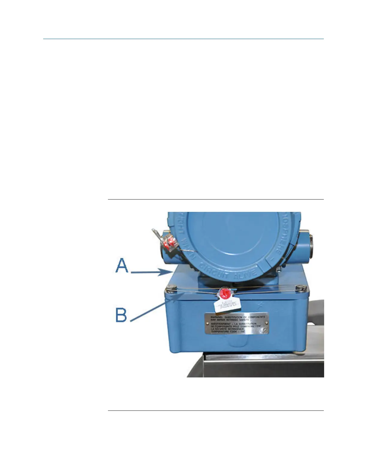
12. If required, install security wire seal into and through the hole in the socket head
screw on the Base Enclosure cover (maximum wire diameter 0.078 inch; 2.0mm).
Base Enclosure wire seal installationFigure 3-21:
A. Base Enclosure cover
B. Security wire seals (optional)
13. Position the wire to prevent counterclockwise rotation of the screws when the seal
wire is taut.
Meter repairs
48 Gas Ultrasonic Flow Meter

 Loading...


