EN Series Drives Manual
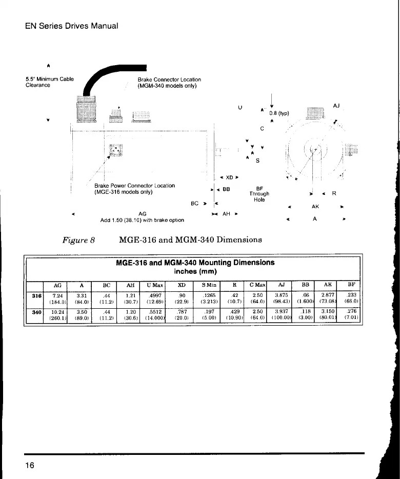
MGE-316 and MGM-340 Mounting Dimensions
inches (mm)
AG
A BC AB
U Max XD
9 Min R C Max
Al BB AK
BF
316
7.24 3.31
.44 1.21 .4997 .90
.1265 .42 2.50
3.875 .06 2.877 .233
(184.0) (84.0)
(11.2) (30.7) (12.69)
(22.9) (3.213) (10.7)
(64.0) (98.43) (1.600)
(73.08' (66.0)
340
10.24 3.50
.44 1.20 .5512 .787
.197 429 2.50
3.937 .118 3.150
.276
(260.1)
(89.0) (11.2) (30.6)
(14.000) (20.0)
(5.00)
(10.90) (64.0) (100.00)
(3.00)
(80.01) (7.01)
5.5" Minimum Cable Brake Connector Location
Clearance (MGM-340 models only)
Brake Power Connector Location
(MGE-316 models only)
BC a
AG
Add 1.50 (38.10) with brake option
A
C
Y y
"
XD a
< BB BF
Through
Hole
a< AH a
Figure 8 MGE-316 and MGM-340 Dimensions
AK
A
R
16
 Loading...