Installation
MGE-455, 490 and 4120 Mounting Dimensions
inches (mm)
AG
A BC All U Max XD S Min R C Max
AJ BB AK BF
455
8.61
5.00 .53 190 .6245 1.50 .1875 .51 3.20 5.875
.10 4.500 3/8-16
(218.7) (127.0) (13.5) (48.2) (15.862) (38.1) (4.763)
(13.0) (81.3) (149.23) (2.50) (114.30 UNC
490 11.11 5.00 .53 190 .8750 1.50 .1875 .77 3.20 5.875 .10 4.500 3/8-16
(282.11:r (127.0) (13.5) (48.2)
(22.225) (38.1) (4.763)
(19.6) (81.3) (149.23 (2.50) (114.30
UNC
4120
13.61 5.00 .53 190
.8750 1.50 .1875 .77 3.20 5.875 .10 4.500 3/8-16
(345.70 (127.0)
(13.5)
(48.2)
(22.225)
(38.1)
(4.763) (19.6) (81.3) (149.23;
(2.50) (114.30. UNC
MGM-455, 490 and 4120 Mounting Dimensions
mm ( nches)
AG
A BC All U Max XD S Min
R C Max AJ BB AK BF
455 216.0 121.0 139 50.5
19.000 40.0 6.00 15.5 70.3 145.00 3.00 11 0.10 10.00
(8.59) (4.764) (.51) (1.99) (.7480) (1.58)
(.236) (.61) (2.77) (5.709) (.118) (4.331) (.394)
490
281.7 121.0 13.0 50.5 24.000
37.1 7.963 19.9 70.3 145.00 3.00 110.10 10.00
(11.09) (4.764)
(.51) (1.99) (9.449) (1.46) (.3135) (.78) (2.77) (5.709) (.118) (4.331)
(.394)
4120 343.1 121.0 13.0 50.5 24.000 37.1
7.963 199 70.3 145.00 3.00 110.10 10.00
(13.59) (4.764) (.51) (1.99) (9.449) (1.46)
(.3135) (.78) (2.77) (5.709) (.118) (4.331) (.394)
A
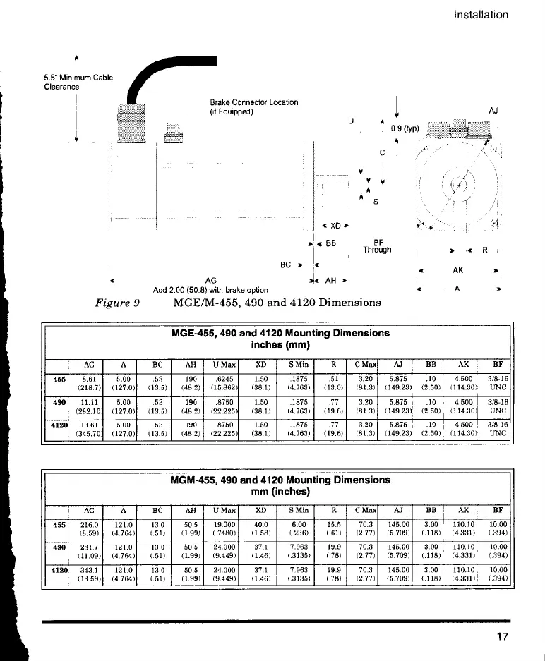
5.5" Minimum Cable
Clearance
Brake Connector Location
(if Equipped)
XD
3 4, BB BF
Through
BC 3.
AG 34c AH 3
Add 2.00 (50.8) with brake option
Figure 9 MGE/M-455, 490 and 4120 Dimensions
U
A
31.
AK
A
17
 Loading...