EN Series Drives Manual
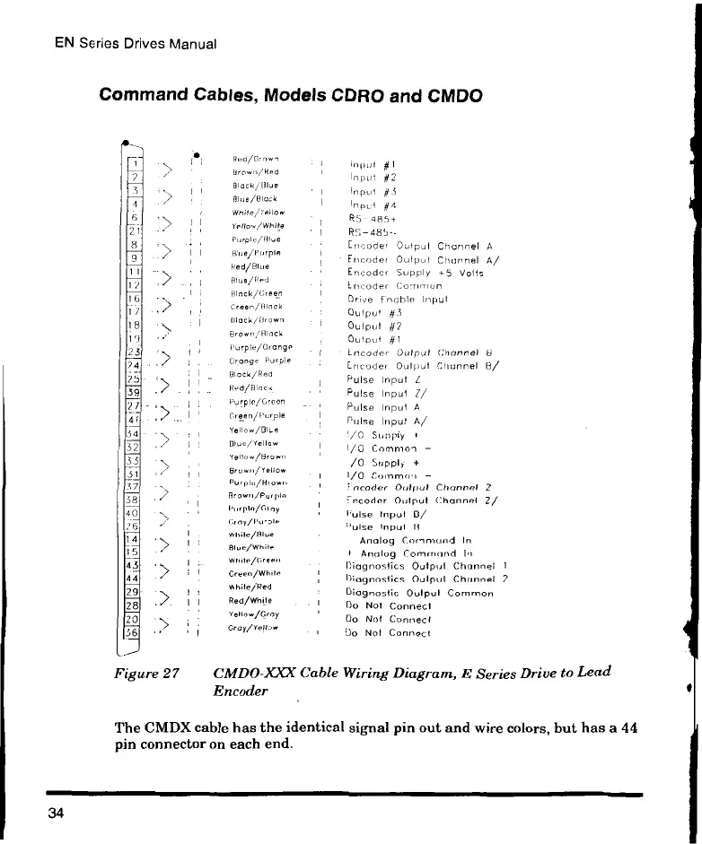
Command Cables, Models CDRO and CMDO
36
Red/F own
Brown/Red
Black/Blue
Waite/Yellow
Yet l aw/ Whq e
Purple/Blue
BIlle/P4rple
Red/Blue
Blue/Red
Black/Breen
Creen/HInck
Black/Brown
Brown/RInck
Purple/Orange
Orange Purple
Black/Red
Red/Hlac,
Purple/Green
Green/Purple
Yel l ow/ Blu e
Blue/Yellow
Yel 1 ow/ Bro wy
Brown/Yellow
Brown/Purp14
Purple/:ray
G,ny/I'Lra,
while/Blue
Blue/While
Wrilte/cree"
Green/While
While/Red
Red/While
veliow/Gray
Gray/Yell,w
1,0y4- #1
Input #2
Input #.5
Input #4
RS 485+
65-4814—
Encoder Output Channel A
Encoder Oulpul Channel A/
Encoder Supply 45 Volts
Encoder Common
Drive Enable Input
Qui pu, #3
Output #2
01.110l11 #1
Gncoder Output Channel
ncoder Output Churn& 8/
Pulse Input
Pulse Input Z/
Pulse Input A
Pulse Input A/
70 Supply
I/O Common -
/0 Supply +
I/O Common -
coder Output Channel
Sncoder Output Channel Z/
Pulse Input IV
'ulse Input li
Analog Cornmond In
t Analog Command In
Diagnostics Output Channel
Diagnostics Output Channel
Diagnostic Output Common
Do Not Connect
Do Not Connect
Do Not Connect
2
Figure 27 CMDO-W Cable Wiring Diagram, E Series Drive to Lead
Encoder
The CMDX cable has the identical signal pin out and wire colors, but has a 44
pin connector on each end.
34
 Loading...