13
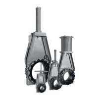
CLARKSON SLURRY KNIFE GATE VALVES
KGA+
Visual inspection of parts prior to reassembly
1. Check and ensure all housing interior
surfaces and drain ports are free and clear
of hardened slurry or other obstructions.
Clean as required.
2. Inspect the valve housing ensuring that the
bores at the center of the valve are aligned
with each other. Check the bore diameter
for wear per Table 4. Replace if there are
signs of excessive or unusual wear.
3. Examine exterior housing surfaces for
buildup of hardened slurry or other
contamination, clean as required.
4. Examine sleeves for signs of wear, cracking,
chunking, deep cuts, severe abrasion or
chemical attack (softening or gumming).
Replace if in doubt; sleeves must be
replaced as a set.
5. Examine secondary seal for signs of wear
or cracking, severe abrasion or chemical
attack (softening or gumming). Replace if
indoubt.
6. Inspect the gate for sharp edges or
excessive damage. Some scoring will
occur in normal use. If the gate has been
bent beyond
1
/
16” (1.5 mm) permanent
deflection at the center, straighten or
replace. If straightening is performed,
use considerable care to minimize
marks on gate surface. Scores or other
distress marks may be cleaned up
with a belt sander. Machining the gate
surface is not recommended. Light
scale buildup may be removed with a
putty knife or gasketscraper. Inspect
the gate for wear and roughness.
Reassembly
1. Lay the first housing half face down on
asuitable flat surface.
2. Carefully lay two new housing gaskets on
face of housings. Gaskets may be held
in place with a small amount of silicone
lubricant placed between gasket and
housing.
3. Take second housing and place into position
on the first housing, and properly align bolt
holes making sure spacer plates remain
inplace.
4. Insert most of the housing bolts,
leaving out the top bolts that are
used to hold the actuator assembly
to the housing and loosely tighten.
Gate
Secondary seal retainer
Secondary seal
Housing bolts/nuts bolts
Retainer flange
Housing
Housing gasket
Sleeve
Retainer flange bolts/nuts
FIGURE 12
Use a disc grinder or belt sander to remove
rough surfaces. Take particular care on the
leading and beveled edge to remove burrs
and other sharp edges.
7. Examine frame for signs of corrosion,
damage or other potential problems.
8. Check all bolting hardware for thread
integrity, signs of corrosion, straightness,
etc. Replace as required.
9. Examine actuator assembly.
A) Manual valves: check stem for
corrosion, straightness, etc. Look for
signs of wear on brass stem nut.
B) Air or hydraulic: check for seal leaks
around cylinder rod seal, heads and
caps. Examine cylinder rod for signs of
corrosion, straightness, etc. Service per
manufacturer’s instructions.
C) Electric motor: service per
manufacturer’s instructions.
Tap the edges of the housings to align the
internal sleeve bores to within
1
/
16” (1.5 mm),
at the same time maintaining bolt hole
alignment in the square flanges.
5. Install new sleeves and retainer flanges
(if used) per instruction in Section ‘Sleeve
replacement’.
6. Lift the valve assembly to vertical position.
Refer to Lifting, Section 15.
7. Using DOW III or approved alternate,
completely fill all internal cavities of the
newsecondary seal.
8. Insert the new lubricated secondary seal
into the valve housing assembly. Make sure
that the lube path openings on the seal line
up with corresponding external housing
lubrication fittings.
9. Place the secondary seal retainer plate
intoposition.
10. Replace and hand tighten all the retainer
plate fasteners and lockwashers.
 Loading...


