iii
FIGURES
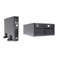
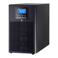
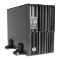
Figure 1 Liebert GXT3-700RT230 - GXT3-3000RT230 UPS 5
Figure 2 Rear panel components, Liebert GXT3 230V 700VA, 1000VA and 1500VA models 5
Figure 3 Rear panel components, Liebert GXT3 230V 2000VA models 5
Figure 4 Rear panel components, Liebert
®
GXT3
™
230V 3000VA models 6
Figure 5 Operating principle diagram 6
Figure 6 Support bases 10
Figure 7 Remove the front plastic bezel cover 10
Figure 8 Rotate the operation and display panel 11
Figure 9 Tower installation 11
Figure 10 Pulling inner member from each bracket assembly 12
Figure 11 Installing rear member of each bracket assembly 13
Figure 12 Installing front member of each bracket assembly 13
Figure 13 Fastening rear member and front member together 13
Figure 14 Installing inner members 14
Figure 15 Installing rack-mount ears 14
Figure 16 Insert the UPS 14
Figure 17 Operation and display panel 17
Figure 18 Battery level indicators 18
Figure 19 Load level indicators 18
Figure 20 Terminal Block Communication pin layout 24
Figure 21 Removing the front plastic bezel cover and battery door 26
Figure 22 Disconnecting the battery plug and battery connector (front view) 27
Figure 23 Pulling out the battery 27
Figure 24 Battery level indicator 29
Figure 25 Battery cabinet 32
TABLES
Table 1 UPS models, power ratings 4
Table 2 Specification of input circuit breaker 15
Table 3 Functions of the On/Alarm Silence/Manual Battery Test button 17
Table 4 Functions of the Standby/Manual Bypass button 17
Table 5 UPS status indicators 19
Table 6 Output voltage option, all models 23
Table 7 Replacement battery pack model numbers 26
Table 8 Indicator descriptions 29
Table 9 Audible alarm description 30
Table 10 Troubleshooting table 30
Table 11 Specifications of GXT3-700RT230 and GXT3-1000RT230 UPS 33
Table 12 Specifications of the Liebert
®
GXT3
™
-1500RT230, GXT3-2000RT230 and GXT3-3000RT230 34
Table 13 Operating temperature parameters 35
Table 14 Battery cabinet specifications 35
Table 15 Battery run times 36