Communication System Manual
UPS System: HIPULSE E
(Modbus/Jbus Interface) Electrical installation
Page 3-4
(04/07)
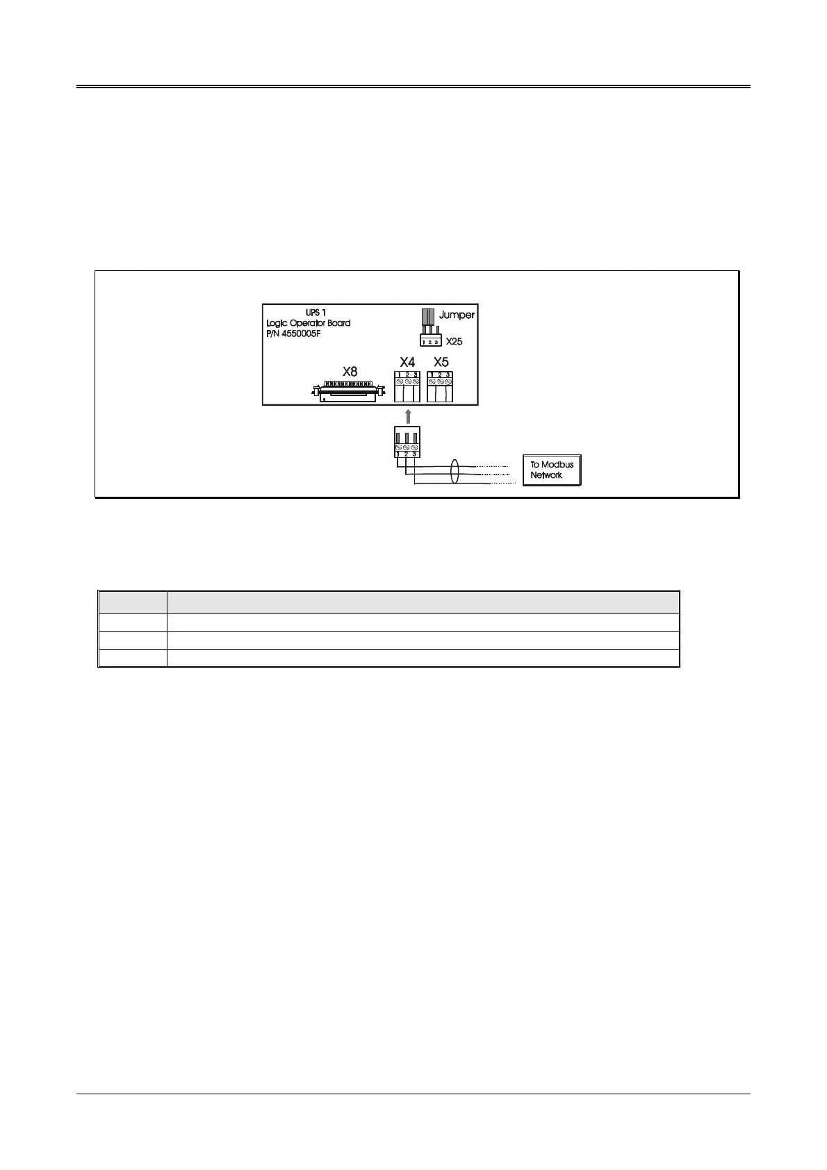
3.1.1 RS-485 electrical connection with Modbus network
There is a male 3-way X4 connector for connection with the Modbus network (BMS) on the bottom of the board. To
make the connection, connect a two-wire shielded cable (supplied by others) to the X4 terminal board of the Operator
Logic Board, unless a multipoint connection is required (described in the following paragraph). The female terminal
connector (on X4) is supplied. The wire must have a section of at least 0.25 mm
2
. The cable must comply with the
requirements of ANSI TIA/EIA-485-A standards.
The RS-485 connection cable must finish at each end with a jumper inserted on the Operator board at position X25 1-2;
in the figure below, this must be done on UPS 1 and on the initial connection at the start of the Modbus network.
Figure 3-4 RS-485 Connection
The following signals are present:
Pin Description
1 TX+ (RX+) is conventionally the positive wire
2 TX- (RX-) is conventionally the negative wire
3 COM is the ground wire
Table 3-1
Use of a two-wire shielded cable with very thick copper braiding in which the shield forms a third constraining wire
(COM) is COMPULSORY.
The impedance of the double wire must be 120 OHMS, in accordance with the RS485 standard.