Menu Flowcharts – Model 1700/2700 IS Transmitters
Model 1700/2700 IS Display CodesModel 2700 CIOModel 1700/2700 AN
Configuration and Use Manual 221
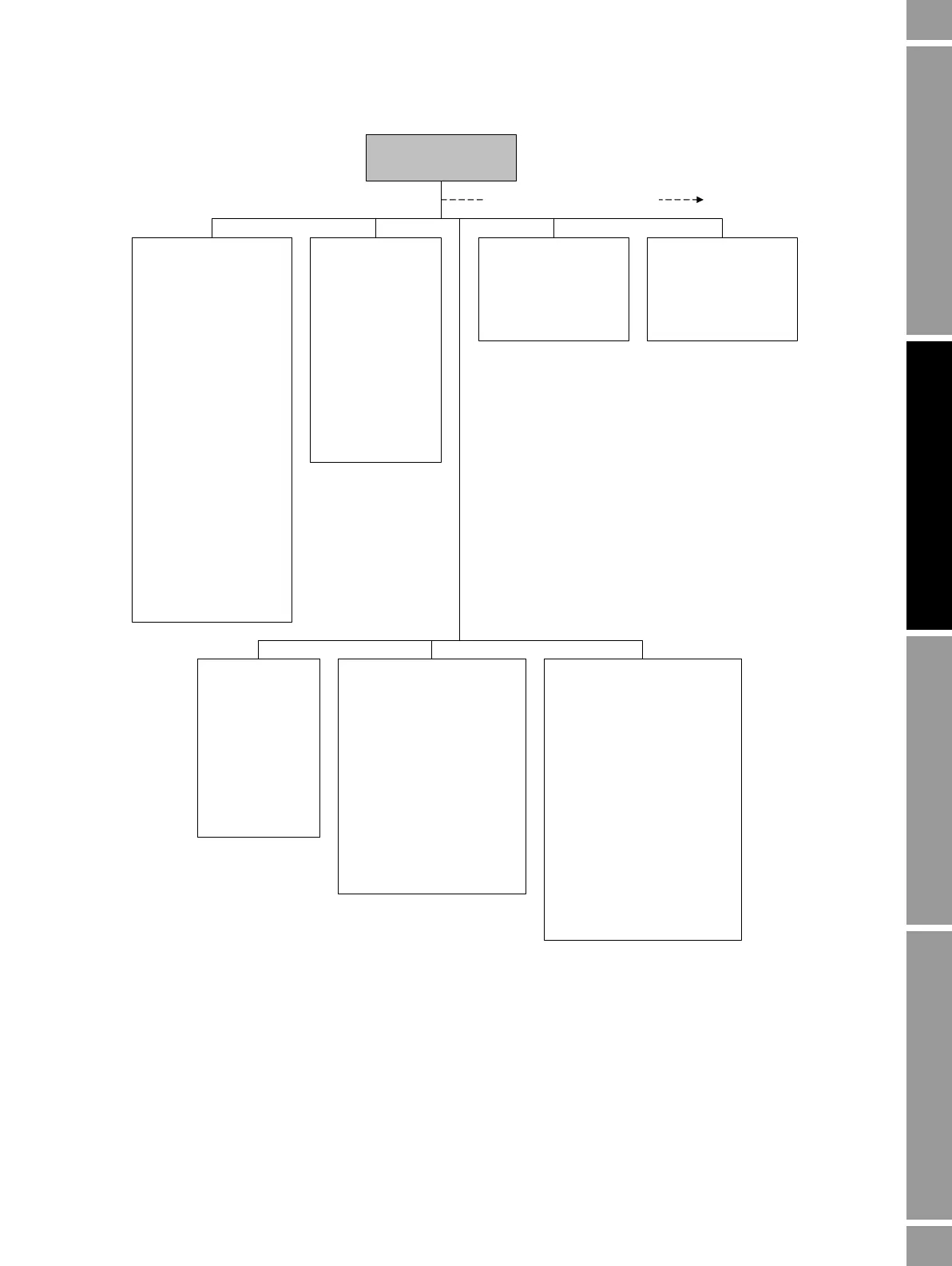
Figure F-2 ProLink II configuration menu
Flow
• Flow direction
•Flow damp
•Flow cal
• Mass flow cutoff
• Mass flow units
• Vol flow cutoff
• Vol flow units
• Vol flow type
• Std gas vol flow cutoff
• Std gas flow units
• Std gas density
Gas wizard
• Mass factor
• Dens factor
• Vol factor
• Flow switch variable
• Flow switch setpoint
• Enable entrained air
handling
Density
• Dens units
• Dens damping
• Slug high limit
• Slug low limit
• Slug duration
• Low density cutoff
•K1
•K2
•FD
•D1
•D2
• Temp coeff (DT)
Temperature
• Temp units
• Temp cal factor
• Temp damping
• External temperature
Analog output
Primary/secondary output
• PV/SV is
• Lower range value
• Upper range value
• AO cutoff
• AO added damp
•LSL
•USL
•Min Span
• AO fault action
• AO fault level
• Last measured value timeout
Frequency/Discrete output
Frequency
• Tertiary variable
• Scaling method
•Freq factor
• Rate factor
• Pulses per unit
• Units per pulse
• Freq pulse width
• Last measured value timeout
• Freq fault action
• Freq output polarity
Discrete output
• DO assignment
•DO polarity
• DO fault action
ProLink >
Configuration
Additional configuration options
Pressure
•Flow factor
• Dens factor
• Cal pressure
• Pressure units
T Series
• FTG
• FFQ
•DTG
•DFQ1
•DFQ2
•K3
•D3
•D4
•K4

 Loading...


