222 Micro Motion Series 1000 and Series 2000 Transmitters
Menu Flowcharts – Model 1700/2700 IS Transmitters
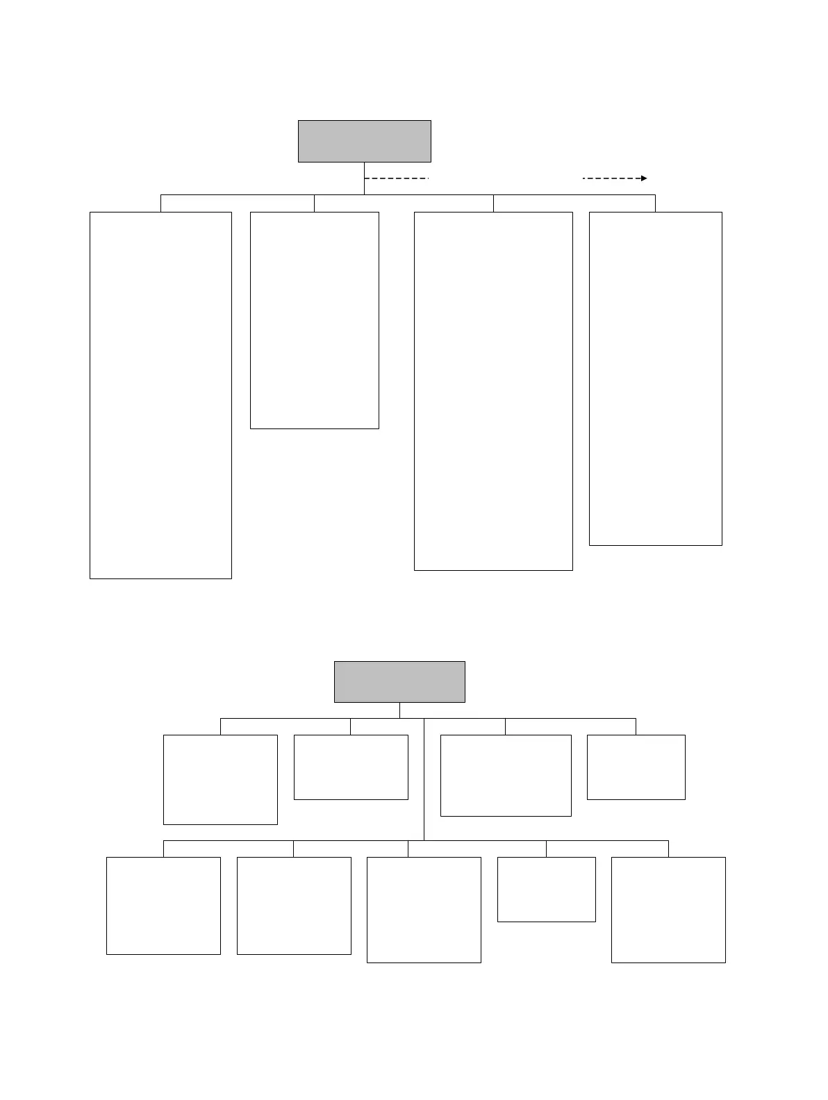
Figure F-3 ProLink II configuration menu continued
Figure F-4 ProLink II configuration menu continued
Device
•Tag
•Date
•Descriptor
• Message
• Sensor type
• Floating pt ordering
• Add comm resp delay
• Transmitter serial number
Digital comm settings
• Fault setting
• HART address
• Loop current mode
• HART device ID
• Modbus address
• Enable write protect
Update rate
• Update rate
• 100 Hz variable
Burst setup
• Enable burst
•Burst cmd
• Burst var 1...4
ProLink >
Configuration
Display
•mA1
• Var2...Var15
Display precision
•Var
• Number of decimals
• Display language
Display options
• Display start/stop totalizers
• Display totalizer reset
• Display auto scroll
• Display offline menu
• Display offline password
• Display alarm menu
• Display ack all alarms
• Display backlight on/off
• Display alarm screen pwd
• Display LED blinking
• Offline password
• Auto scroll rate
• Update period
Additional configuration options
Special Units
• Base mass unit
• Base mass time
• Mass flow conv fact
• Mass flow text
• Mass total text
• Base vol unit
• Base vol time
• Vol flow conv fact
• Vol flow text
• Vol total text
• Gas unit configurator
Sensor simulation
• Enable/disable
Mass flow
• Wave form
• Fixed value
•Period
• Minimum
• Maximum
Density
• Wave form
• Fixed value
•Period
• Minimum
• Maximum
Temperature
• Wave form
• Fixed value
•Period
• Minimum
• Maximum
ProLink >
Configuration
Transmitter options
• Volume flow
• Meter fingerprinting
• Meter verification
Variable mapping
• PV is
• SV is
•TV is
•QV is
System
• W & M approval
• Reset options
Sensor
•Sensor s/n
•Sensor model
•Sensor matl
• Liner matl
•Flange
Alarm
•Alarm
•Severity
Events
• Event 1/2
•Variable
•Type
•Setpoint
Discrete events
• Event name
• Event type
• Process variable
• Low setpoint (A)
• High setpoint (B)
Polled variables
Polled variable 1/2
• Polling control
•External tag
• Variable type
• Current value
Discrete input
• Assignment
•Polarity

 Loading...


