Flow
• Flow direction
•Flow damp
•Flow cal
• Mass flow cutoff
• Mass flow units
• Vol flow cutoff
• Vol flow units
• Vol flow type
• Std gas vol flow cutoff
• Std gas flow units
• Std gas density
Gas wizard
• Mass factor
• Dens factor
• Vol factor
• Enable entrained air
handling
• Flow switch variable
• Flow switch setpoint
Density
• Density units
• Density damping
• Slug high limit
• Slug low limit
• Slug duration
• Low density cutoff
•K1
•K2
•FD
•D1
•D2
• Temp coeff (DT)
Temperature
• Temp units
• Temp cal factor
• Temp damping
• External temperature
Pressure
•Flow factor
• Dens factor
• Cal pressure
• Pressure units
• External pressure
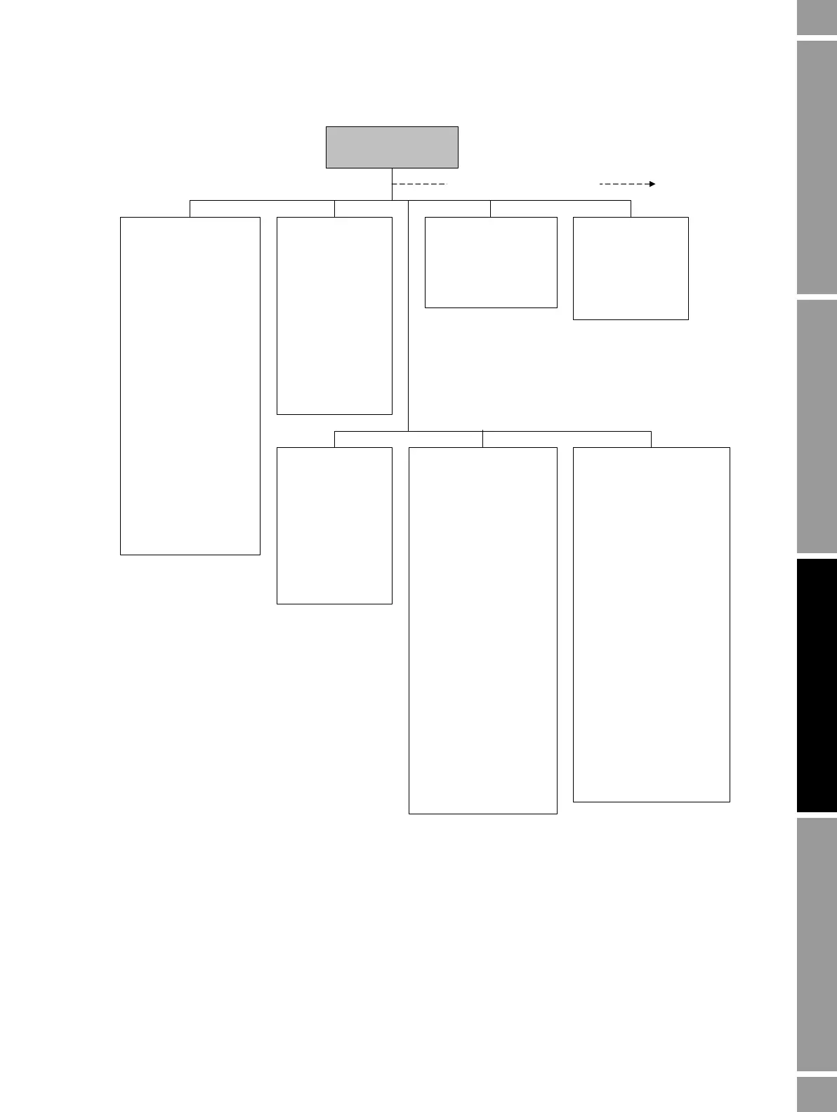
ProLink >
Configuration
Additional configuration options
Device
•Tag
•Date
•Descriptor
• Message
• Sensor type
• Transmitter serial number
• Floating pt ordering
• Add comm resp delay
Digital comm settings
• Fault setting
• HART address
• Loop current mode
• HART device ID
• Modbus address
• Enable write protection
Update rate
• Update rate
•100 Hz variable
Burst setup
• Enable burst
• Burst cmd
• Burst var 1...4
T Series
• FTG
• FFQ
•DTG
•DFQ1
•DFQ2
•K3
•D3
•D4
•K4
Display
• Var1...Var15
Display precision
•Var
• Number of decimals
Display language
Display options
• Display start/stop totalizers
• Display totalizer reset
• Display auto scroll
• Display offline menu
• Display offline password
• Display alarm menu
• Display ack all alarms
• Display backlight on/off
• Display alarm screen
password
• Display status LED blinking
• Offline password
• Auto scroll rate
• Update period

 Loading...


