Safety
Information
Product
Information
Mechanical
Installation
Electrical
Installation
Getting
Started
Basic
parameters
Running the
Motor
Optimization
SMARTCARD
Operation
Onboard
PLC
Advanced
Parameters
Technical
Data
Diagnostics
UL
Information
Quantum MP User Guide 139
Issue: A4 www.emersonct.com
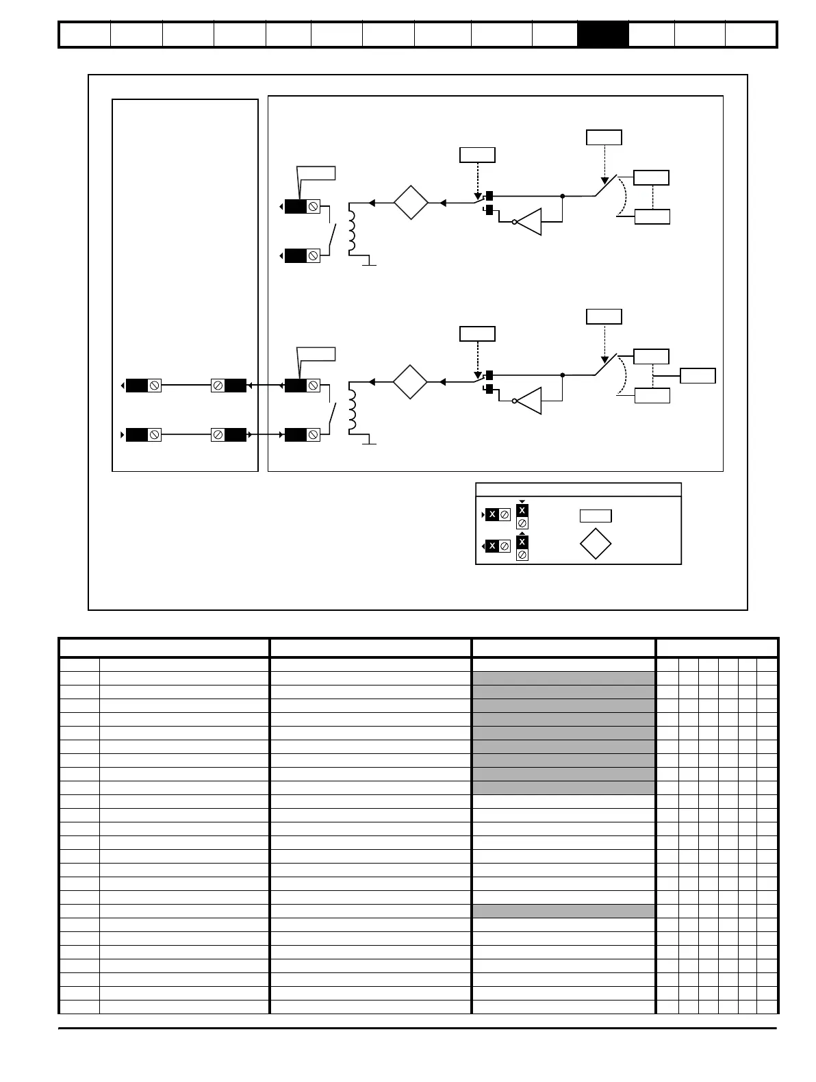
Figure 11-21 Relay logic diagram
0.XX
0.XX
Key
Read-write (RW)
parameter
Read-only (RO)
parameter
Input
terminals
Output
terminals
12
11
Relay 2
0V
C16
X1
Q12
Q11
??.??
??.??
Relay 2
source
Any bit or
integer
parameter
Contactor
enable
17.28
Relay 2
invert
17.18
x(-1)
17.08
Relay 2
state
6.55
10
11
Relay 1
0V
??.??
??.??
Relay 1
source
Any bit or
integer
parameter
17.27
Relay 1
invert
17.17
x(-1)
17.07
Relay 1
state
The parameters are all shown at their default settings
MP 10
User Interface Board
SM-I/O120V in Slot 3
Parameter
Range(
) Default()
Type
17.01 Solutions Module ID 0 to 599 206 RO Uni PT US
17.02 Solutions Module software version 0.00 to 99.99
RO Uni NC PT
17.03 T4 digital input 3 state OFF (0) or ON (1)
RO Bit NC PT
17.04 T5 digital input 4 state OFF (0) or On (1)
RO Bit NC PT
17.05 T7 digital input 5 state OFF (0) or On (1)
RO Bit NC PT
17.06 T8 digital input 6 state OFF (0) or On (1)
RO Bit NC PT
17.07 Relay 1 state OFF (0) or On (1)
RO Bit NC PT
17.08 Relay 2 state OFF (0) or ON (1)
RO Bit NC PT
17.09 T1 digital input 1 state OFF (0) or ON (1)
RO Bit NC PT
17.10 T2 digital input 2 state OFF (0) or ON (1)
RO Bit NC PT
17.11 T1 digital input 1 invert OFF (0) or ON (1) OFF (0) RW Bit US
17.12 T2 digital input 2 invert OFF (0) or ON (1) OFF (0) RW Bit US
17.13 T4 digital input 3 invert OFF (0) or ON (1) OFF (0) RW Bit US
17.14 T5 digital input 4 invert OFF (0) or ON (1) OFF (0) RW Bit US
17.15 T7 digital input 5 invert OFF (0) or ON (1) OFF (0) RW Bit US
17.16 T8 digital input 6 invert OFF (0) or ON (1) OFF (0) RW Bit US
17.17 Relay 1 invert OFF (0) or ON (1) OFF (0) RW Bit US
17.18 Relay 2 invert OFF (0) or ON (1) OFF (0) RW Bit US
17.20 Digital I/O read word 0 to 255
RO Uni NC PT
17.21 T1 digital input 1 destination PR 0.00 to PR 21.51 PR 6.39 RW Uni DE US
17.22 T2 digital input 2 destination PR 0.00 to PR 21.51 PR 6.34 RW Uni DE US
17.23 T4 digital input 3 destination PR 0.00 to PR 21.51 PR 6.31 RW Uni DE US
17.24 T5 digital input 4 destination PR 0.00 to PR 21.51 PR 6.33 RW Uni DE US
17.25 T7 digital input 5 destination PR 0.00 to PR 21.51 PR 10.33 RW Uni DE US
17.26 T8 digital input 6 destination PR 0.00 to PR 21.51 PR 0.00 RW Uni DE US
17.27 Relay 1 source PR 0.00 to PR 21.51 PR 0.00 RW Uni US