Reference Manual
00809-0100-4716, Rev JA
May 2008
Rosemount 3095 MultiVariable
2-18
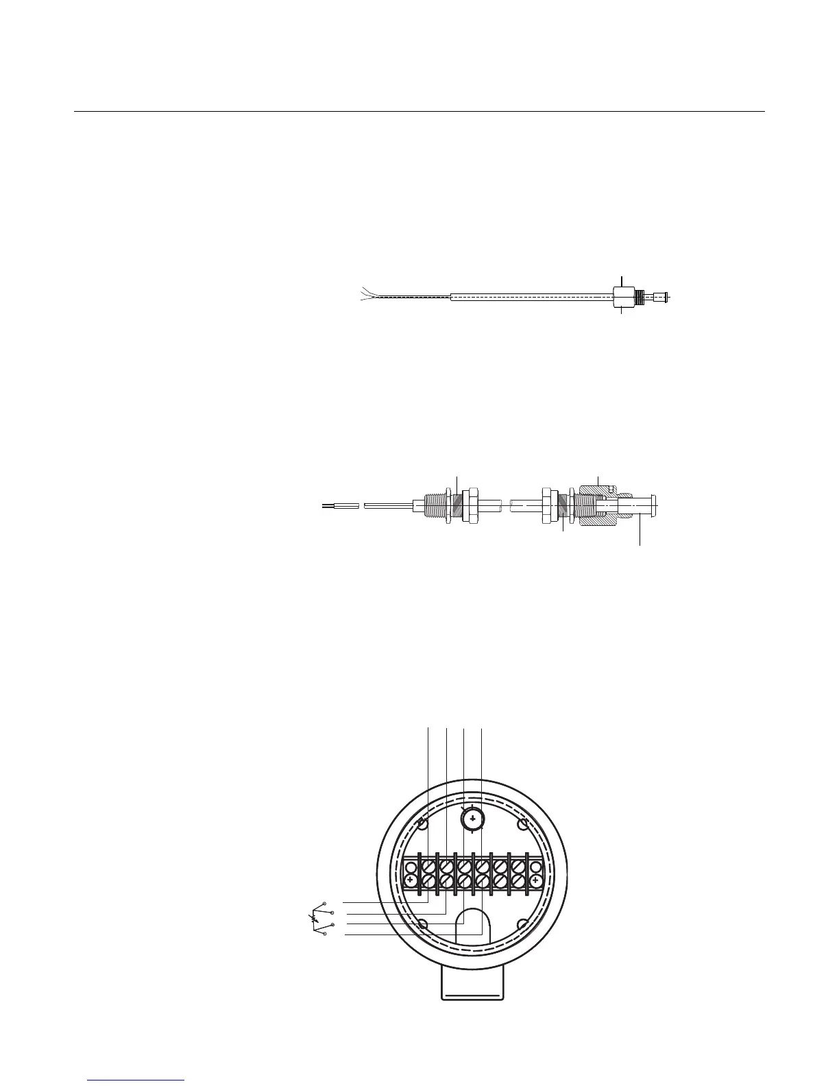
• Installing a Shielded 3095 RTD Cable (intended for use in a conduit)
a. Fully engage the black cable connector to the 3095 RTD
Connector (see Figure 2-9).
b. Tighten the cable adapter until metal contacts metal (see
Figure 2-9).
Figure 2-9. Shielded RTD Cable
• Installing a CENELEC Flameproof 3095 RTD Cable
a. Fully engage the black cable connector to the 3095 RTD
Connector (see Figure 2-10).
b. Tighten the cable adapter and cable gland until metal contacts
metal (see Figure 2-10).
Figure 2-10. CENELEC
Flameproof RTD Cable
c. Make all necessary wiring connections inside the RTD Flat
Connection Head as explained in the Sensor Wiring Instructions
included with the RTD.
Figure 2-11 illustrates typical wiring configuration of the Rosemount RTC
Cable Assembly to a 4-wire RTD.
Figure 2-11. RTD Sensor Wiring Diagram
Cable Adapter
1
/2–14 NPT
Black Cable Connector
Black Cable Connector
Cable Adapter
Cable Gland
RTD Cable Gland CM20
RTD Cable
Assembly Wires
Red
Red
White
White
A
A
B
B
3095_23A.EPS




 To Next Page