Reference Manual
00809-0100-4716, Rev JA
May 2008
Rosemount 3095 MultiVariable
2-10
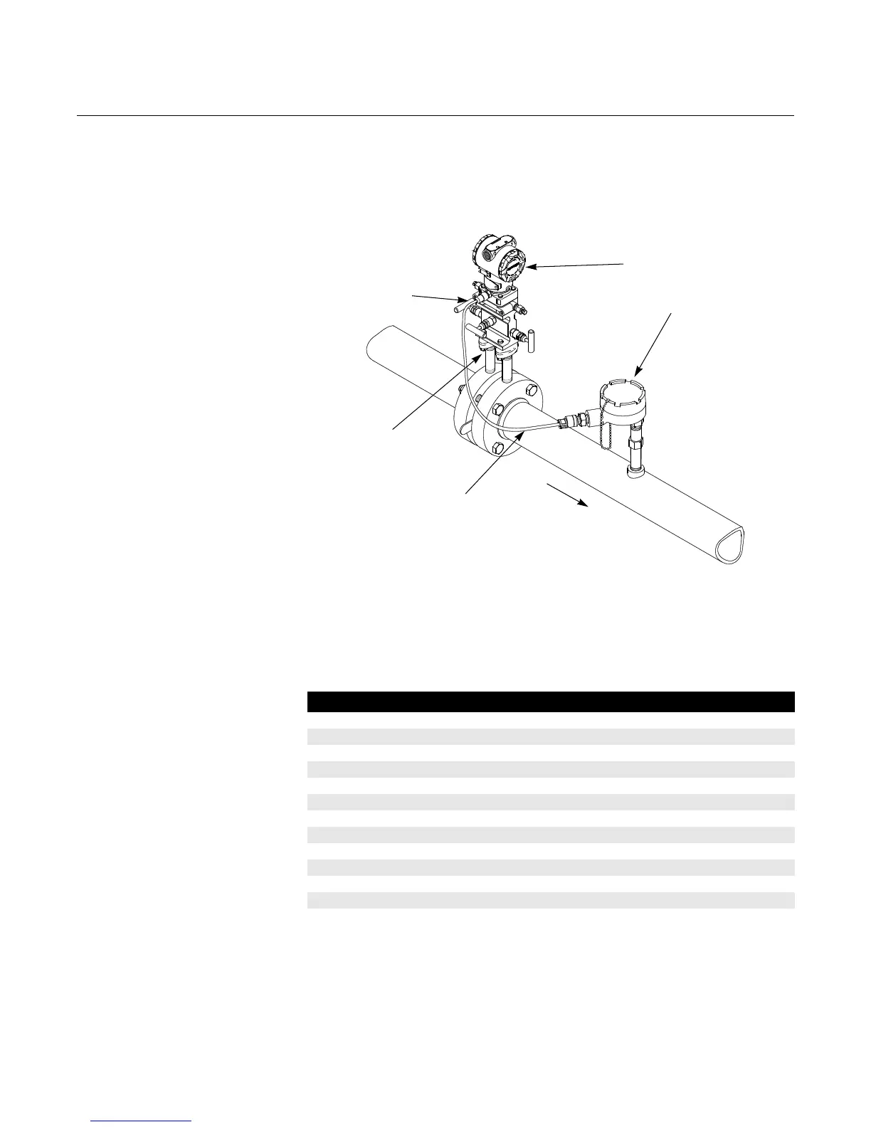
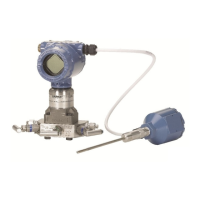
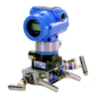
Mounting Figure 2-4 illustrates a typical 3095 installation site. Major components of the
3095 System and the 3095 Multivariable Transmitter are identified in these
figures.
Figure 2-4. Typical 3095
Installation Site
The 3095 Multivariable Transmitter total weight varies depending on the
components ordered (see “Ordering Information” on page A-11). The weight
must be securely supported.
Table 2-1. Transmitter Weight
3095
RTD Connector
Process
Connections
RTD Cable
RTD
Assembly
Flow
Component Weight lb (kg)
3095 Transmitter 6.0 (2.7)
SST Mounting Bracket 1.0 (0.4)
12 ft (3.66 m) RTD Shielded Cable 0.5 (0.2)
12 ft (3.66 m) RTD Armored Cable 1.1 (0.5)
24 ft (7.32 m) RTD Shielded Cable 1.0 (0.4)
24 ft (7.32 m) RTD Armored Cable 2.2 (1.0)
75 ft (22.86 m) RTD Shielded Cable 1.9 (0.9)
75 ft (22.86 m) RTD Armored Cable 7.2 (3.2)
21 in (53 cm) RTD Armored Cable 0.5 (0.2)
12 ft (3.66 m) RTD CENELEC Cable 2.1 (0.9)
24 ft (7.32 m) RTD CENELEC Cable 3.0 (1.4)
75 ft (22.86 m) RTD CENELEC Cable 7.1 (3.2)
21 in (53 cm) RTD CENELEC Cable 1.2 (0.5)




 To Next Page