Reference Manual
00809-0100-4716, Rev JA
May 2008
Rosemount 3095 MultiVariable
2-14
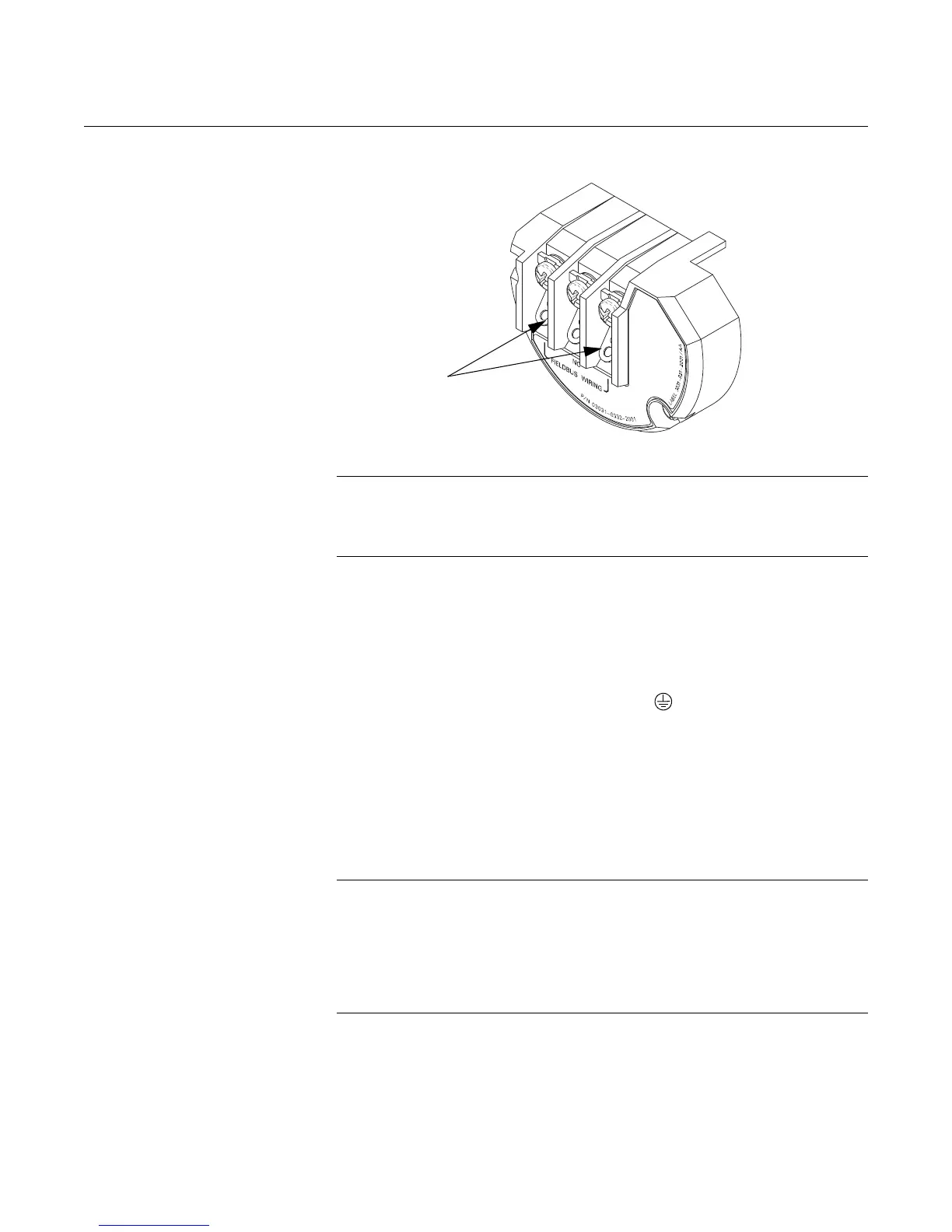
Figure 2-7. FOUNDATION
Fieldbus Transmitter Terminal
Block
NOTE
Do not ground out the live signal wiring to the housing when working on a
segment. Grounding the communication wires may result in temporary loss of
communication with all devices on the segment.
Grounding the
Transmitter Housing
Always ground the transmitter case in accordance with national and local
electrical codes. The most effective transmitter case grounding method is a
direct connection to earth ground with minimal impedance. Methods for
grounding the transmitter case include:
• Internal Ground Connection: The Internal Ground Connection screw
is inside the FIELD TERMINALS side of the electronics housing. The
screw is identified by a ground symbol ( ), and is standard on all
3095 transmitters.
• External Ground Assembly: This assembly is included with the
optional transient protection terminal block (Option Code T1), and it is
included with CESI/CENELEC Flameproof Certification (Option Code
E8), BASEEFA/CENELEC Intrinsic Safety Certification (Option Code
I1), and BASEEFA/CENELEC Type N Certification (Option Code N1).
The External Ground Assembly can also be ordered with the
transmitter (Option Code V5), or as a spare part (03031-0398-0001).
NOTE
Grounding the transmitter case using the threaded conduit connection may
not provide a sufficient ground. The transient protection terminal block (Option
Code T1) does not provide transient protection unless the transmitter case is
properly grounded. Use the above guidelines to ground the transmitter case.
Do not run transient protection ground wire with signal wiring; the ground wire
may carry excessive current if a lightning strike occurs.
Surges/Transients The transmitter will withstand electrical transients of the energy level usually
encountered in static discharges or induced switching transients. However,
high-energy transients, such as those induced in wiring from nearby lightning
strikes, can cause damage to the transmitter.

 Loading...