Reference Manual
00809-0100-4716, Rev JA
May 2008
2-13
Rosemount 3095 MultiVariable
NOTE
Do not apply high voltage (e.g. ac line voltage) to the transmitter terminals.
Abnormally high voltage can damage the unit.
Grounding
Signal wiring of the fieldbus segment cannot be grounded. Grounding out one
of the signal wires will shut down the entire fieldbus segment.
Shield Wire Ground
To protect the fieldbus segment from noise, grounding techniques for shield
wire usually require a single grounding point for shield wire to avoid creating a
ground loop. The ground point is typically at the power supply.
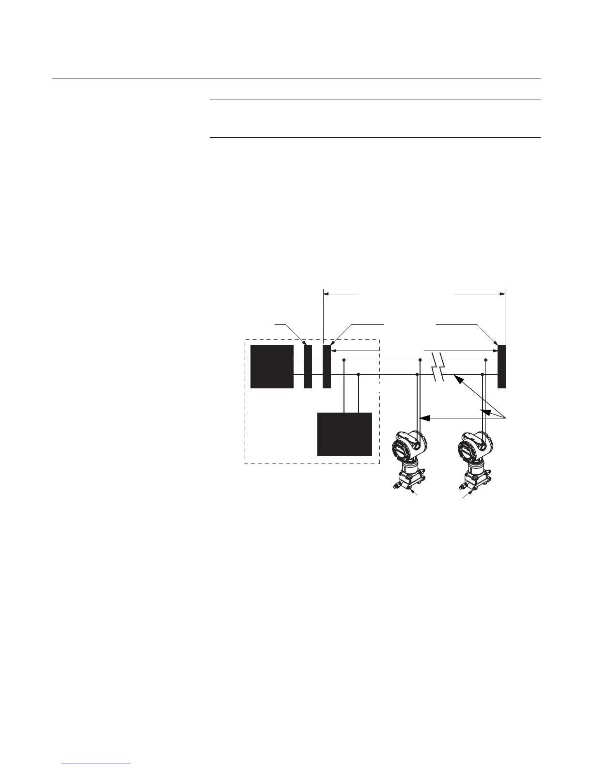
Figure 2-6. FOUNDATION
Fieldbus Wiring Connections
Power Connections
Use ordinary copper wire of sufficient size to ensure that the voltage across
the transmitter power terminals does not go below 9 V dc. To power the
transmitter, connect the power leads to the terminals marked “FIELDBUS
WIRING” as shown in Figure 2-7. The power terminals are polarity
insensitive, which means the electrical polarity of the power leads does not
matter when connecting to the power terminals. When wiring to screw
terminals, the use of crimped lugs is recommended. Tighten the terminal
screws to ensure adequate contact.
6234 ft (1900 m) max
(depending upon cable
characteristics)
Terminators
Fieldbus
Segment
(Trunk)
Spur
(Spur)
Power
Supply
FOUNDATION
fieldbus
Configuration
Tool
(The power supply
filter, first
terminator, and
configuration tool
are typically
located in the
control room.)
Integrated Power
Conditioner
and Filter
Signal
Wiring
fieldbus
devices on
segment
*Intrinsically safe installations may allow fewer devices per I.S. barrier due to current limitations.