Reference Manual
00809-0100-4716, Rev JA
May 2008
Rosemount 3095 MultiVariable
2-20
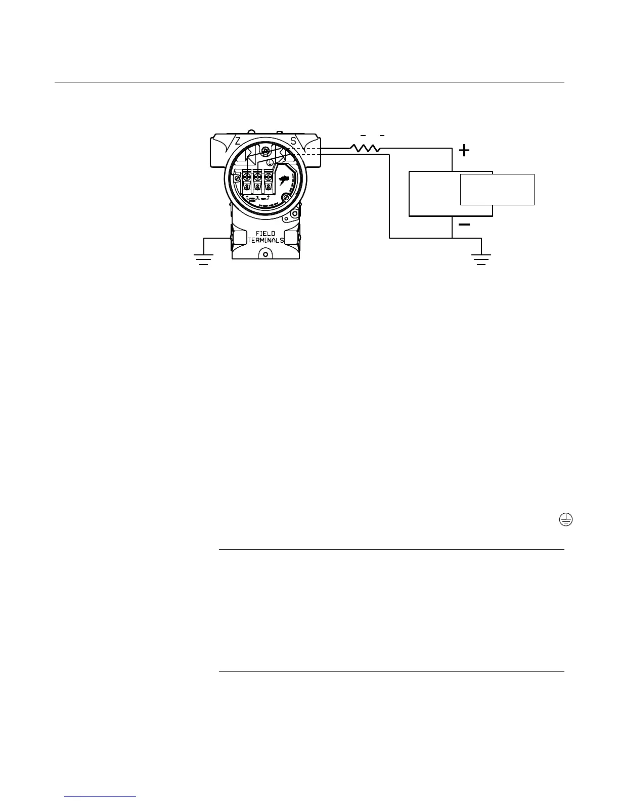
Figure 2-12. HART Wiring
Connections.
Field Wiring Ground
a. Field wiring may be grounded at any one point on the signal loop,
or it may be left ungrounded. The negative terminal of the power
supply is a recommended grounding point.
Ground the Transmitter Case
b. The transmitter case should always be grounded in accordance
with national and local electrical codes. The most effective
transmitter case grounding method is direct connection to earth
ground with minimal impedance. Methods for grounding the
transmitter case include:
• External Ground Assembly: This assembly is included with the
transient protection terminal block. The External Ground
Assembly can also be ordered as a spare part (see “Spare
Parts List” on page A-14).
• Internal Ground Connection: Inside the FIELD TERMINALS
side of the electronics housing is the Internal Ground
Connection screw. This screw is identified by a ground symbol:
NOTE
The transient protection terminal block does not provide transient protection
unless the transmitter case is properly grounded. Use the above guidelines to
ground the transmitter case.
Do not run the transient protection ground wire with field wiring as the ground
wire may carry excessive current if a lighting strike occurs.
Grounding the transmitter case using threaded conduit connection may not
provide sufficient ground.
8. Replace the cover.
1100 > R
L
> 250
User-Provided
Power Supply
Signal loop may be grounded at
any point or left ungrounded
(see step 7.a).
(see step 7.b)




 To Next Page