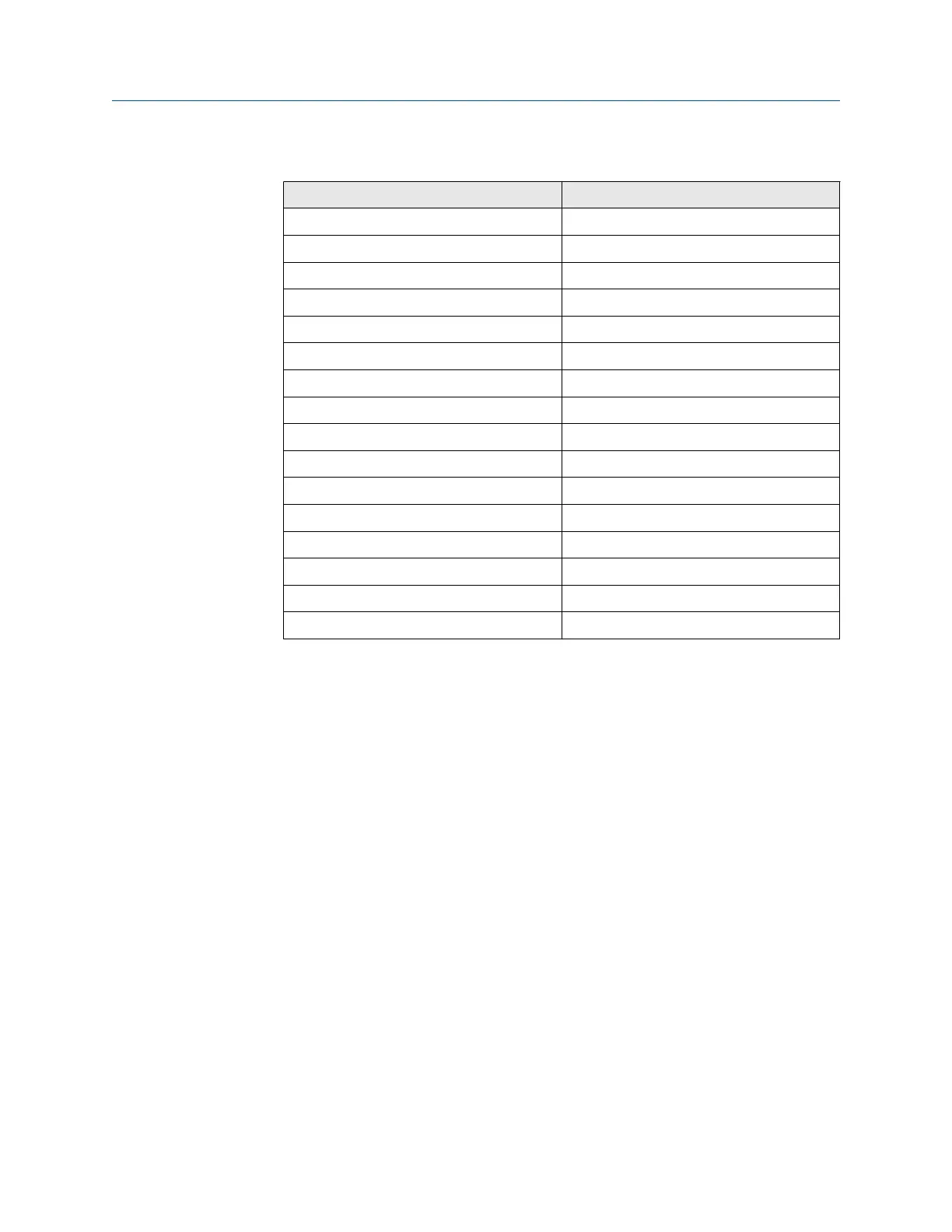
Table 10-1: Sensor Housing Terminal Connections
(continued)
Wire color Connects to
Black CJC-
Orange CJC+
White CO reference-
Red CO reference+
Black CO act-
Brown CO act+
Yellow Exc+
Blue O
2
+
Black O
2
-
Black Heater O
2
2
Orange Heater O
2
1
Yellow Heater CO 2
Red Heater CO 1
White Heater SB 2
Blue Heater SB 1
Green Ground screw
5. Disconnect the signal cable from the O
2
and T/C terminal blocks and from
the CO and CJC terminal blocks.
6. Disconnect the heater power cable from the heater terminal blocks.
7. If moving the sensor housing to another work site, disconnect and remove
the power and signal cables from the sensor housing.
8. Remove insulation to access the mounting bolts. Unbolt the sensor housing
from the stack and take it to a clean work area.
9. Allow the sensor housing to cool to a comfortable working temperature.
Install sensor housing
Procedure
1. Connect the test gas, reference air, eductor air, and dilution air lines to the
sensor housing.
2. Remove the sensor housing cover.
3. If removed, install the power and signal cables and the customer power and
signal conduits and wiring at the sensor housing.
4. Connect the signal cable to O
2
and thermocouple (T/C) terminal blocks and
to the CO and CJC terminal blocks, Figure 10-4. Connect the heater power
cable to the HTR terminal blocks.
Maintenance and service Manual
December 2022 00809-0500-4880
244 Emerson.com/Rosemount