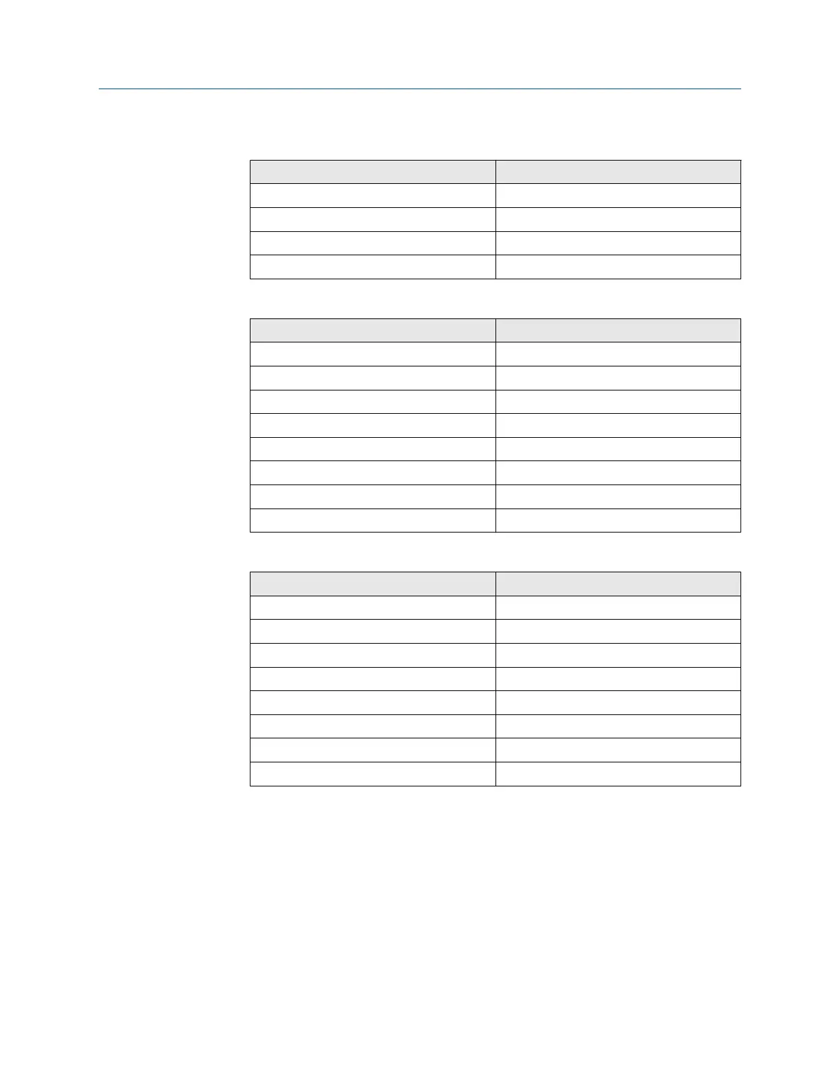
Table 10-5: J3 Connections
(continued)
Wire color Connects to
Black 2 heater O
2
Orange 1 heater O
2
White 2 heater sample block (SB)
Blue 1 heater SB
Table 10-6: J4 Connections
Wire color Connects to
Yellow Exc+
Brown CO act-
Black CO act+
Red CO reference+
White CO reference-
Orange CJC+
Black CJC-
Black Exc-
Table 10-7: J5 Connections
Wire color Connects to
Red Thermocouple (T/C) CO+
Black T/C CO-
White T/C SB+
Black T/C SB-
Green T/C O
2
+
Black T/C O
2
-
Blue O
2
cell+
Black O
2
cell-
Install local operator interface (LOI) module and board
Procedure
1. Install LOI board (F, Figure 10-25) and secure it with two screws (G) and
lockwashers (H).
2. Note the location of the LOI connector (P). Plug LOI module (D) and
connector into one of the four mating receptacles provided.
3. Install three screws (E) to secure the LOI module.
Manual Maintenance and service
00809-0500-4880 December 2022
Rosemount OCX8800A 287