Emerson Process Management GmbH & Co. OHG 2-11
X-STREAM Non-Incendive
Instruction Manual
HASXENE-IM-EX
12/2014
2
Installation
• Connect the housing to a ground or equi-
potential bonding conductor.
• Keep all cabels, entering the housing, as
short as possible.
• The cable glands are intended for cables
with an outer diameter of 7 to 12 mm [0.27
to 0.47 in]. Special adapters enabling to
mount thinner or multiple cables in one
connection can be provided on request.
• Supply terminals are intended for cab-
les with a cross section of up to 4 mm
2
[11 AWG]
• Use shielded cables only for signal lines
to ensure electromagnetic compatibility
(EMC).
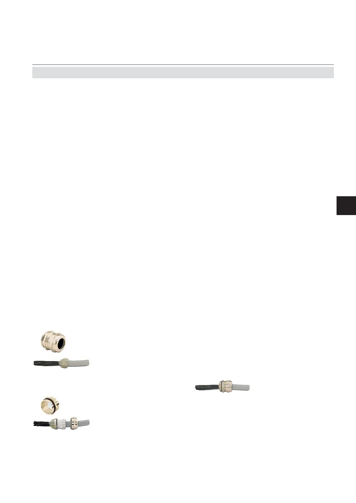
3. Feed cable through
dome nut and clam-
ping insert
4. Fold braided shield
over clamping insert
1. Strip the cabel
2. Expose braided
shield
5. Make sure that brai-
ded shield overlaps
the O-ring by
3
⁄32“
(2 mm)
6. Push clamping insert
into body and tighten
dome nut
7. Assemble into housing
and you´re done!
2.7 Installation - Electrical
Installing cable glands with shielded cables
All signal cables are connected to screw-type
terminals located inside the housing. Access
to the internal components is gained by re-
leasing the two (upper enclosure´s) fasteners
and opening the front panel sidewards.
All cables must be fed through cable glands
and secured with a gland nut.
Preparation of signal cables
Signal in- and outputs
Properly installed, the glands act as a strain
relief and guarantee EMC (electromagnetic
compatibility):

 Loading...


