Emerson Process Management GmbH & Co. OHG 2-13
X-STREAM Non-Incendive
Instruction Manual
HASXENE-IM-EX
12/2014
2
Installation
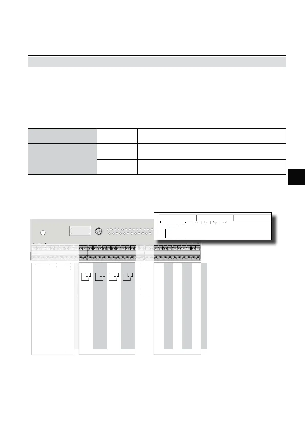
Fig. 2-5: Terminals Block X1 - Analog Signals and Relay Outputs 1-4
Note!
Consider the special installation instructions
in chapter 4 of the X-STREAM gas analyzer
series manuals and the notes on installing
cable glands on page 2-8!
Analog signals
Relay outputs 1 - 4
Terminals for analog signals and relais outputs
1 - 4 are located on the outer left module
(terminal block X1; Fig. 2-5).
**)
Confi guration of relay out-
put terminals as per standard
factory setting (NAMUR
status signals). NAMUR sta-
tus signals are automatically
confi gured Fail Safe!
Pin Signal
P2.1 Channel 1, (+) 4 (0) - 20 mA
P2.2 Channel 1, GND
P2.3 Channel 2, (+) 4 (0) - 20 mA
P2.4 Channel 2, GND
P2.5 Channel 3, (+) 4 (0) - 20 mA
P2.6 Channel 3, GND
P2.7 Channel 4, (+) 4 (0) - 20 mA
P2.8 Channel 4, GND
P2.9 Channel 5, (+) 4 (0) - 20 mA
P2.10 Channel 5, GND
P2.11 not used
P2.12 not used
P3.1 not used
P3.2 not used
P3.3 Output 1 (Failure), NC
P3.4 Output 1 (Failure), NO
P3.5 Output 1 (Failure), COM
P3.6 Output 2 (Maintenance Request), NC
P3.7 Output 2 (Maintenance Request), NO
P3.8 Output 2 (Maintenance Request), COM
P3.9 Output 3 (Out of Spec), NC
P3.10 Output 3 (Out of Spec), NO
P3.11 Output 3 (Out of Spec), COM
P3.12 Output 4 (Function check), NC
P4.1 Output 4 (Function check), NO
P4.2 Output 4 (Function check), COM
P4.3 not used
P4.4
P4.5
P4.6
P4.7
P4.8
P4.9
P4.10
P4.11
P4.12
Relay Outputs
**)
Analog Outputs
Serial Interface
*)
P4.
n
t
P4.4
P4.
P4.
P4.
P4.
P4.
P4.1
P4.1
P4.1
erial Interfac
*
P2.1
n
t
P2.1
n
t
P
.
n
t
P
.
n
t
2.7 Installation - Electrical
Specifi cation of analog
signal outputs:
4 (0) – 20 mA; burden: R
B
≤ 500 Ω
Specifi cation of relay
outputs 1–4:
electrical
specifi cation
max. load. 30 V; 1 A; 30 W resistive
mechancial
specifi cation
Dry relay change-over contacts can be used as NO
or NC
12
11
10
9
8
7
6
5
4
3
2
1
P2
P3
P4
ANALOG OUT
4
ANALOG OUT
2
ANALOG OUT 3
ANALOG OUT 1
GROUND 3
GROUND 1
GROUND 2
GROUND 4
K4
K3
K2 K1
X2
RS 232
RS 485 2W
RS 485 4W
MODBUS
CAN
FF
9- IOIO -1
12
11
10
9
8
7
6
5
4
3
2
1
12
11
10
9
8
7
6
5
4
3
2
1
GROUND 5
ANALOG OUT
5
X

 Loading...


