Emerson Process Management GmbH & Co. OHG 2-17
X-STREAM Non-Incendive
Instruction Manual
HASXENE-IM-EX
12/2014
2
Installation
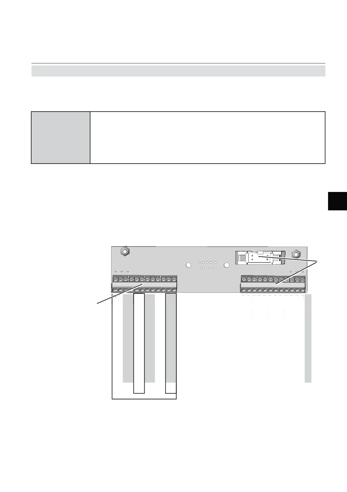
Analog Inputs
Pin Signal
P2.1 not used
P2.2 not used
P2.3 not used
P2.4 not used
P2.5 not used
P2.6 not used
P2.7 not used
P2.8 not used
P2.9 not used
P2.10 not used
P2.11 not used
P2.12 not used
P4.1 BR 1 fi t a wire bridge here to apply analog
P4.2 BR 1 signal in current mode to input 1
P4.3 Input 1 high (+)
P4.4 Input 1 high (+)
P4.5 Input 1 low (-)
P4.6 Input 1 low (-)
P4.7 BR 2 fi t a wire bridge here to apply analog
P4.8 BR 2 signal in current mode to input 2
P4.9 Input 2 high (+)
P4.10 Input 2 high (+)
P4.11 Input 2 low (-)
P4.12 Input 2 low (-)
{
}
{
}
IN1
Mode
IN2
Mode
1 Screw-type terminals
2 Reserved for future use
P4.
P4.
P4.1
1
2
.
n
2.
n
t
2.
n
t
2.4 n
t
2.
n
t
2.
n
t
2.
n
t
2.
n
t
2.
n
t
2.1
n
t
2.1
n
t
2.1
n
t
Fig. 2-9: Terminals Block X5 - Analog Input Signals
Note!
Consider the special installation instructions
in chapter 4 of the X-STREAM gas analyzer
series manuals and the notes on installing
cable glands on page 2-8!
2.7 Installation - Electrical
2 analog inputs
0 – 1 (10) V (software selectable) R
in
= 100 kΩ
optional (requires to fi t wire bridges, see fi gure):
4 (0) – 20 mA ; R
in
= 50Ω
optically isolated from analyzer GND
protected against overload up to ±15 V or ±20 mA
Analog inputs

 Loading...


