Emerson Process Management GmbH & Co. OHG2-14
X-STREAM Non-Incendive
Instruction Manual
HASXENE-IM-EX
12/2014
*)
See table below
Serial Interface
Specifi cation and interface control:
Analyzer instruction manual, chapter 9
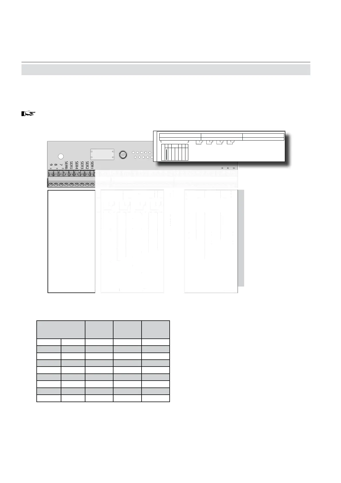
The 9 terminals on the left (28 - 36) of the
strip next to the power connections carry the
Modbus interface signals.
Notes!
Consider the special installation instruc-
tions in chapter 4 of the X-STREAM gas
analyzer series manuals and the notes
on installing cable glands on page 2-8!
X-STREAM analyzers are classifi ed as
DTE (Data Terminal Equipment).
The type of serial interface is marked
on a label nearby the terminals (see
sample above)
Assignment of serial interface terminals
Fig. 2-6: Terminals Block X1 - Serial Interface
2.7 Installation - Electrical
Pin Signal
P2.1 Channel 1, (+) 4 (0) - 20 mA
P2.2 Channel 1, GND
P2.3 Channel 2, (+) 4 (0) - 20 mA
P2.4 Channel 2, GND
P2.5 Channel 3, (+) 4 (0) - 20 mA
P2.6 Channel 3, GND
P2.7 Channel 4, (+) 4 (0) - 20 mA
P2.8 Channel 4, GND
P2.9 Channel 5, (+) 4 (0) - 20 mA
P2.10 Channel 5, GND
P2.11 not used
P2.12 not used
P3.1 not used
P3.2 not used
P3.3 Output 1 (Failure), NC
P3.4 Output 1 (Failure), NO
P3.5 Output 1 (Failure), COM
P3.6 Output 2 (Maintenance Request), NC
P3.7 Output 2 (Maintenance Request), NO
P3.8 Output 2 (Maintenance Request), COM
P3.9 Output 3 (Out of Spec), NC
P3.10 Output 3 (Out of Spec), NO
P3.11 Output 3 (Out of Spec), COM
P3.12 Output 4 (Function check), NC
P4.1 Output 4 (Function check), NO
P4.2 Output 4 (Function check), COM
P4.3 not used
P4.4
P4.5
P4.6
P4.7
P4.8
P4.9
P4.10
P4.11
P4.12
Relay Outputs
**)
Analog Outputs
Serial Interface
*)
P2.1
n
t
P2.1
n
t
P
.
n
t
P
.
n
t
P
.
utput 1
Failure
, N
P
.4
utput 1
Failure
, N
P
.
utput 1
Failure
,
M
P
.
utput 2
Maintenance Request
, N
P
.
utput 2
Maintenance Request
, N
P
.
utput 2
Maintenance Request
,
M
P
.
utput 3
ut o
pec
, N
P
.1
utput 3
ut of Spec
, N
P
.1
utput 3
ut o
pec
,
M
P
.1
utput 4
Function check
, N
P4.
utput 4
Function check
, N
P4.
utput 4
Function check
,
M
P4.
n
t
ela
utputs
**
P2.
hannel 1,
+
4
0
- 20 mA
P2.
hannel 1,
N
P2.
hannel 2,
+
4
0
- 20 mA
P2.4
hannel 2, GN
P2.
hannel 3,
+
4
0
- 20 mA
P2.
hannel 3,
N
hannel 4,
+
4
0
- 20 mA
P2.
hannel 4,
N
P2.
hannel 5,
+
4
0
- 20 mA
P2.1
hannel 5, GN
Analo
utputs
12
11
10
9
8
7
6
5
4
3
2
1
P2
P3
P4
ANALOG OUT
4
ANALOG OUT
2
ANALOG OUT
3
ANALOG OUT
1
GROUND 3
GROUND 1
GROUND 2
GROUND 4
K4
K3
K2 K1
X2
RS 232
RS 485 2W
RS 485 4W
MODBUS
CAN
FF
9- IOIO -1
12
11
10
9
8
7
6
5
4
3
2
1
12
11
10
9
8
7
6
5
4
3
2
1
GROUND 5
ANALOG OUT
5
X
Terminal
MOD 485/
2 wire
MOD 485/
4 wire
RS 232
P4.4 SER1 Common Common Common
P4.5 SER2 not used not used RXD
P4.6 SER3 not used not used TXD
P4.7 SER4 not used RXD1(+) not used
P4.8 SER5 D1(+) TXD1(+) Common
P4.9 SER6 not used not used not used
P4.10 7 not used not used not used
P4.11 8 not used RXD0(-) not used
P4.12 9 D0(-) TXD0(-) not used

 Loading...


