Commissioning Liquisys M CPM223/253
54 Endress+Hauser
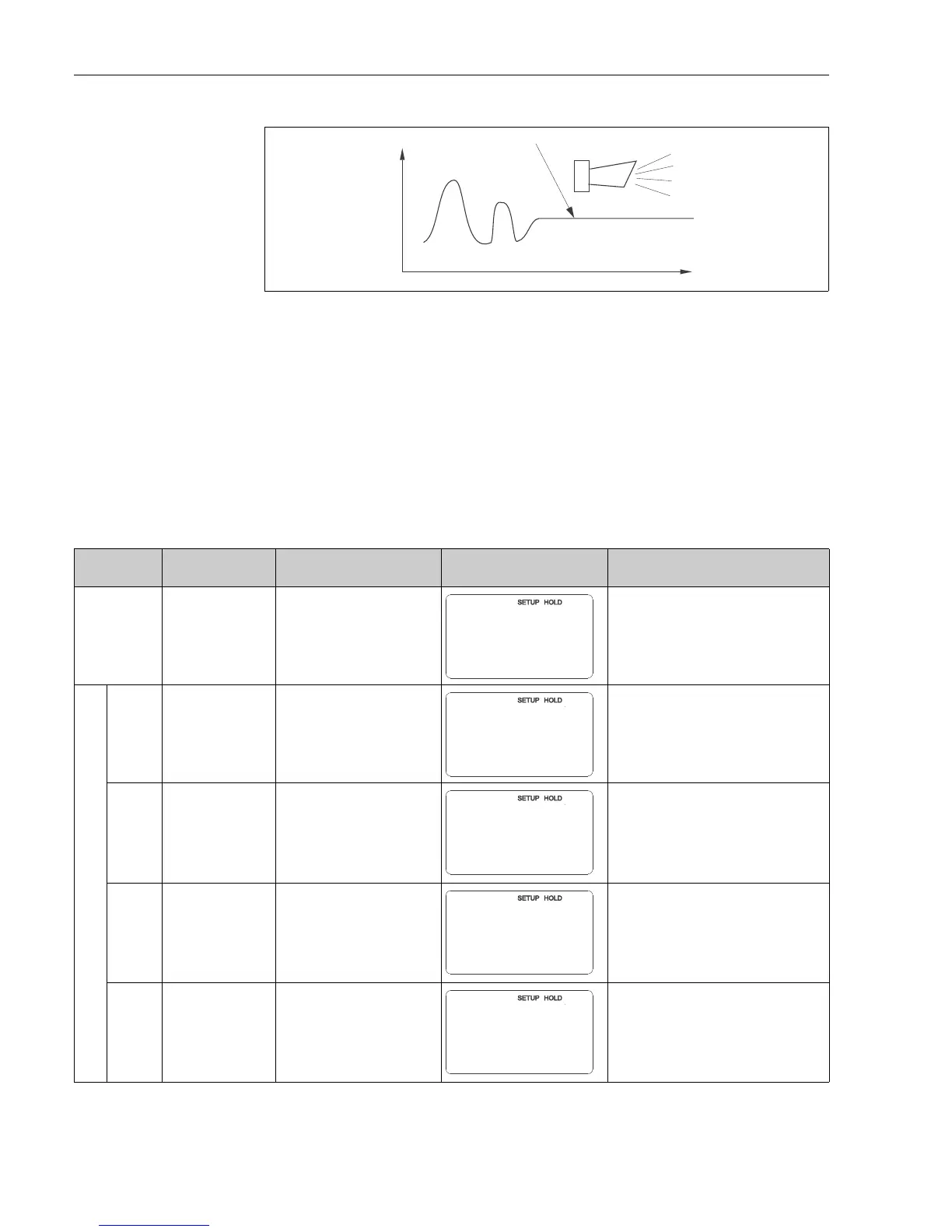
C07-CxM2x3xx-05-06-00-xx-001.eps
Fig. 37: PCS alarm (live check)
A Constant measuring signal = alarm triggered after PCS alarm time has elapsed
Pay attention to the following:
• The electrode must be symmetrically connected (with PML) to monitor the reference.
• Any PCS alarm pending is automatically deleted as soon as the sensor signal changes.
• Due to its semiconductor component, the ISFET sensor is sensitive to light and reacts with
measured value fluctuations. For this reason, avoid direct sunlight when calibrating and
operating. Normal ambient light does not have any effect on the measurement.
Alarm threshold monitoring
You can use this function to monitor the measured value for permissible upper and lower
limits and trigger an alarm.
Coding Field Setting range
(Factory settings, bold)
Display Info
P
CHECK function
group
Settings for electrode and process
monitoring
P1
Switch SCS alarm for
the measuring
electrode on or off
Off
On
Monitoring of electrode for glass breakage
(error no.: E008).
Response time approx. 30 s
SCS glass warning (error no.: E175)
SCS monitoring is not active during
calibration.
P2
Switch SCS alarm for
the reference
electrode on or off
Off
On
Monitoring of reference electrode for
contamination or clogging (error no.:
E030).
Response time approx. 60 s
SCS ref warning (error no.: E177)
Only for A2 = sym.
P3
Enter SCS alarm
threshold for
reference electrode
50.0 k
0.0 to 50 k
The measurement result also contains the
resistance of the medium.
The impedance of the reference electrode
increases with the degree of
contamination.
Not for Memosens
P4
Leak current display
for ISFET sensor
Display only!
0.0 to 9.9 μA
Only if A4 = ISFET.
Leak currents > 0.4 μA indicate damage to
the ISFET sensor.

 Loading...


