The cleaning system is not switched off during calibration or maintenance activities
Risk of injury due to medium or cleaning agent
‣ If a cleaning system is connected, switch it off before removing a sensor from the
medium.
‣ If you are not switching off the cleaning system because you wish to test the cleaning
function, wear protective clothing, goggles and gloves or take other appropriate
measures.
Please clean contamination on the glass electrodes as follows:
• Oily and greasy films:
Clean with detergent (grease dissolvers, such as alcohol, acetone, poss. washing-up
liquids).
Risk of injury caused by cleaning agents
‣ When using the following cleaning agents, make sure to protect your hands, eyes and
clothing!
• Lime and metal hydroxide layers:
Dissolve layers with diluted hydrochloric acid (3 %) and then rinse carefully with a lot of
clear water.
• Layers containing sulphide (from flue gas desulphurizing or sewage treatment plants):
Use mixture of hydrochloric acid (3 %) and thiocarbamide (usual commercial) and then
rinse carefully with a lot of clear water.
• Layers containing proteins (e.g. food industry):
Use mixture of hydrochloric acid (0.5 %) and pepsin (usual commercial) and then rinse
carefully with a lot of clear water.
ORP sensors:
Carefully clean the metal pins or surfaces mechanically.
After mechanical cleaning, the ORP sensor can require several hours conditioning time.
For this reason, check the calibration after a day.
ISFET sensors
• When cleaning ISFET sensors, do not use any acetone as this can damage the material.
• After cleaning with compressed air, ISFET sensors need approx. 5 to 8 minutes until the
closed-control loop is reestablished and the measured value is adjusted to the real value.
Clogged diaphragms can be cleaned mechanically (does not apply to Teflon diaphragms
and open ring junction electrodes):
• Use a small warding file.
• Only file in one direction.
Air bubbles in the electrode:
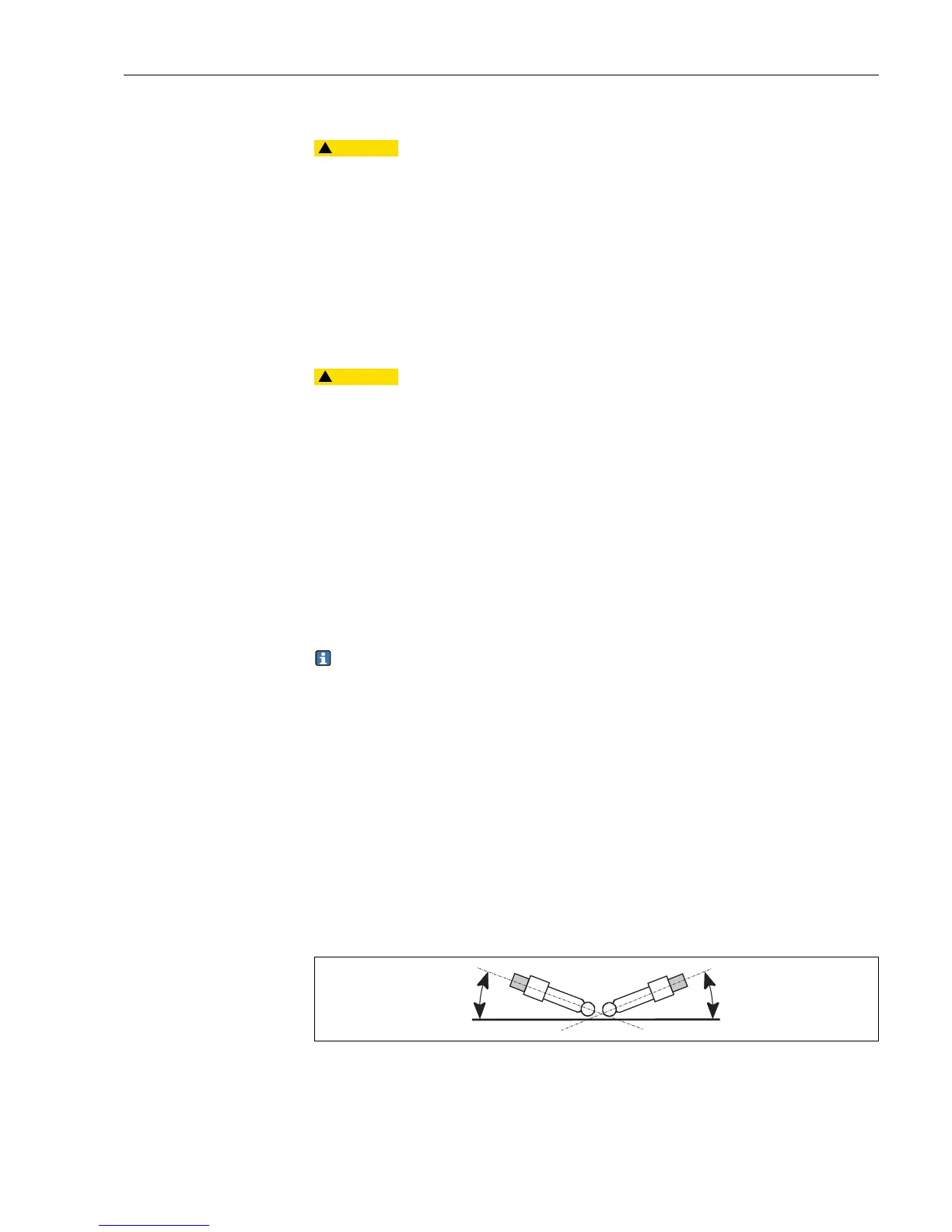
• Air bubbles can indicate incorrect mounting. For this reason check the orientation.
• The range 15 to 165 to the horizontal is allowed.
• Not permitted: horizontal installation or installation with the plug-in head pointing
downwards.
C07-CPM2x3xx-05-06-00-xx-006.eps
Fig. 46: Permitted angle of installation for glass electrodes

 Loading...


