Installation
Hardware Installation and Maintenance Manual 3
–17
Tochange4‐20mAboardfromsourcetosink(AnalyzerAorB)
1. Disconnect power from the analyzer and open the electronics
enclosure cover. Take care not to disturb the electrical assembly
inside.
2. Locate the relay control board in the upper right of the electronics
enclosure, as shown in Figure 1–6 on page 1–11 or Figure 1–7 on
page 1–12 (Analyzer A) or Figure 1–8 on page 1–13 or Figure 1–9
on page 1–14 (Analyzer B).
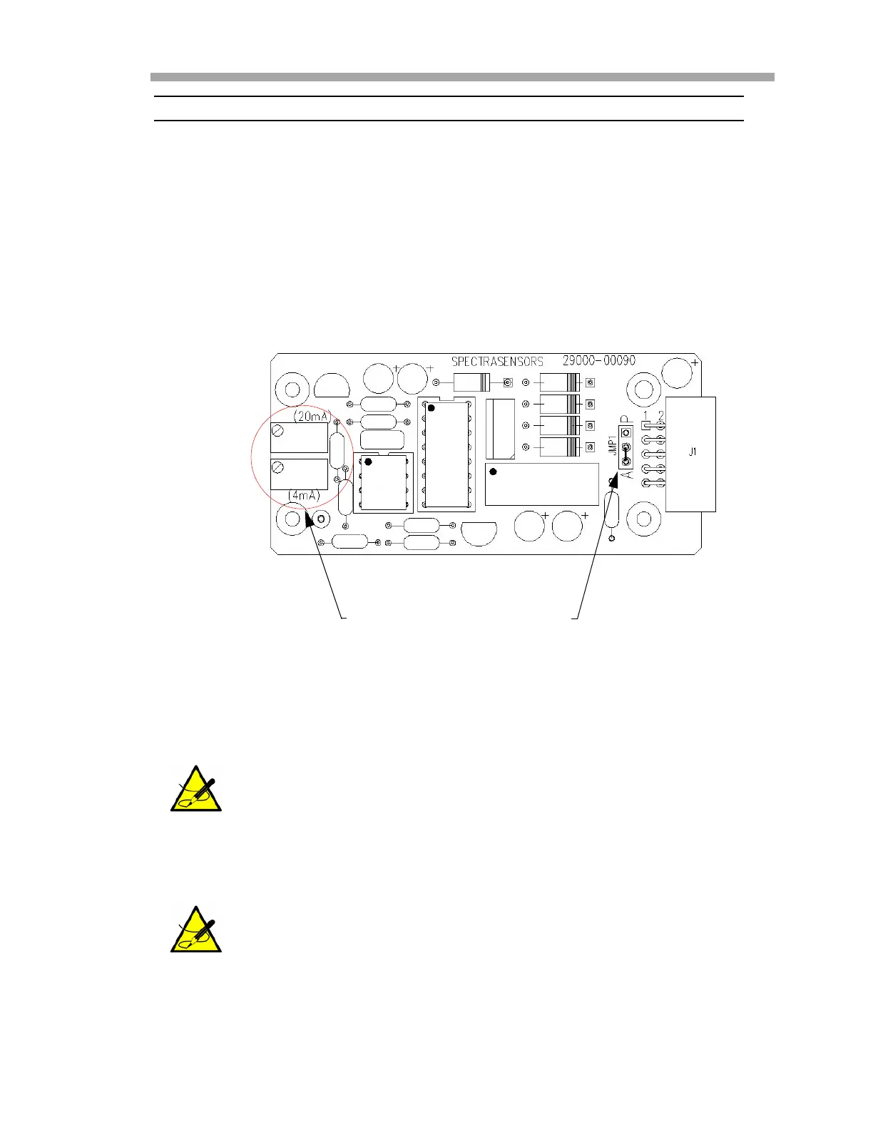
3. Remove the jumper (JMP1), shown in Figure 3–8 on page 3–17,
connecting the center pin to point “A.”
4. For 4-20 mA sink, carefully replace the jumper to connect the center
hole with point “P.”
5. Reconnect power to the analyzer. Confirm the 4 mA (minimum) and
20 mA (maximum) points.
6. Close and tighten the analyzer electronics enclosure cover.
Needle nose pliers may be required to remove the jumper.
For Analyzer A, see “To calibrate the analog output (Analyzer
A)” on page 3-18. For the Analyzer B, refer to “To calibrate the
analog output (Analyzer B)” on page 3-18.
Figure 3–8 Analyzer 4-20 mA board
JMP1POTENTIOMETERS
 Loading...


