Maintenance and Service
Safety Manual 5
–5
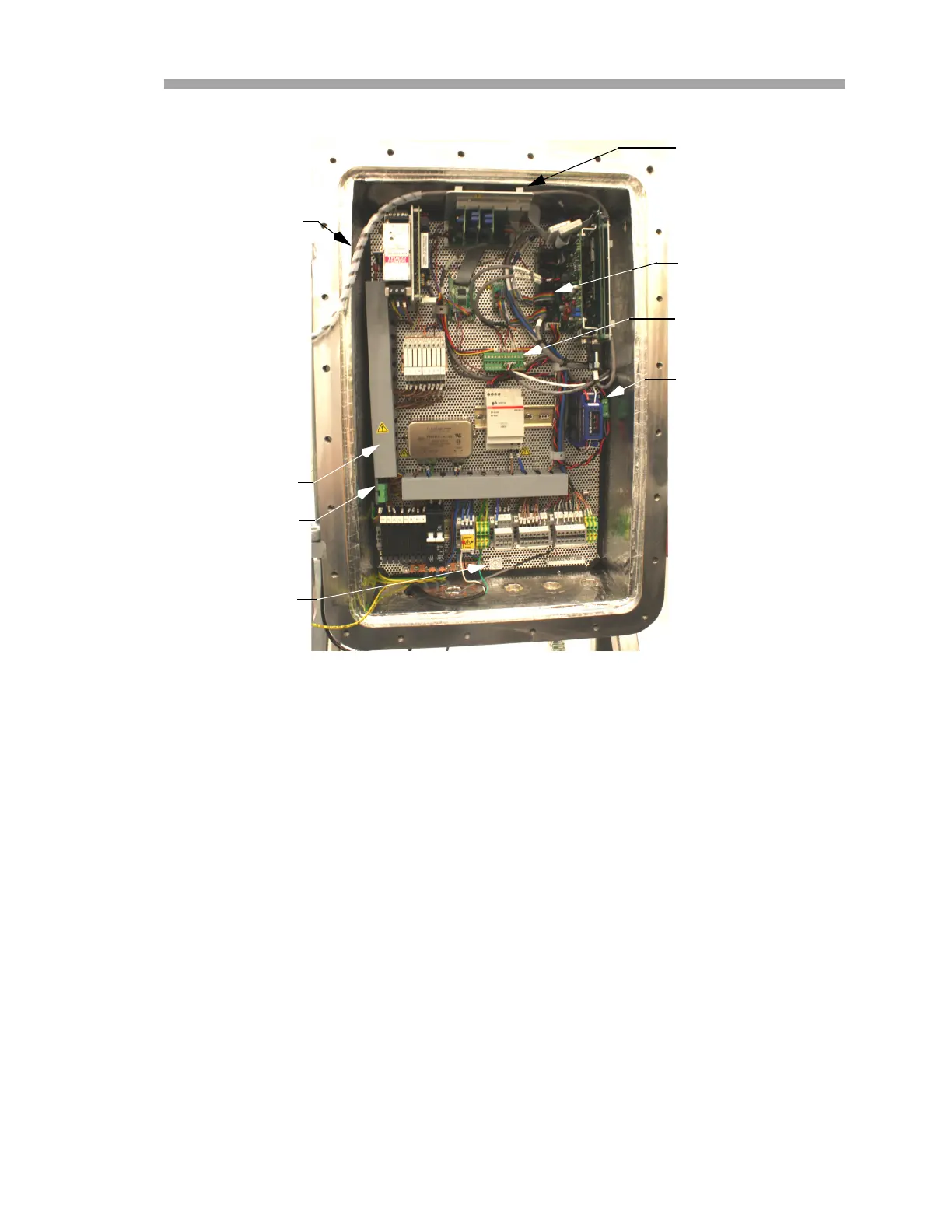
6. Disconnect the optical head cable.
7. Disconnect the temperature/pressure cables by removing the green
connector block.
8. Slide the wire duct cover at the left of the enclosure towards the top
and disconnect the heater power terminal.
9. Disconnect the Watlow controller. Remove the four mounting screws
from the four corners of the electronics panel and set them aside.
You are now ready to remove the electronics panel.
10. Gently pull the electronics panel towards you, away from the
enclosure, tilting the panel forward slightly to lift up and over the
wires connected at the base of the enclosure.
11. Support the electronics panel without completing removing it from
the enclosure. Refer to Figure 5–5.
TEMPERATURE/
PRESSURE CABLES
WATLOW
CONTROLLER QUICK
CONNECT
WIRE DUCT
COVER
HEATER POWER
TERMINAL
KEYPAD/
DISPLAY CABLE
CLIPS
OPTICAL HEAD
CABLE
KEYPAD/
DISPLAY CABLE
Figure 5–4 Electronics assembly panel
PROTECTIVE
GROUND

 Loading...


