Maintenance and Service
Safety Manual 5
–7
1. Discard used scrubber and scrubber indicator in an appropriate leak-
proof receptacle.
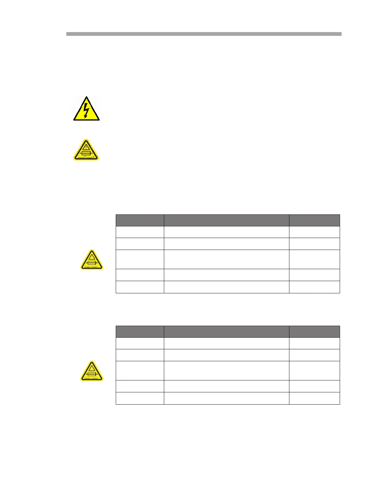
Fuse Ratings and Characteristics
Refer to Figure 5–2 for an illustration of the fuse location in the electronics
assembly.
Hazardous voltage and risk of electric shock. Turn off and lock out
system power before opening the electronics enclosure and
making any connections.
If you need to replace a fuse, use only the same type and rating
of fuse as the original. Refer also to specifications listed in
Table 5–1 or Table 5–2.
Table 5–1 Fuse specifications for 240 VAC systems
DWG Ref. Description Rating
F3 Miniature Fuse, 5 x 20 mm, Time Delay 250 VAC/1.6 A
F4
1
1. Housed in fused terminal blocks. Illuminated LED indicates blown fuse.
Miniature Fuse, 5 x 20 mm, Time Delay 250 VAC/0.5 A
F5
1
,F6
1
,
F7
1
,F8
1
Miniature Fuse, 5 x 20 mm, Time Delay 250 VAC/0.1 A
F9
1
Miniature Fuse, 5 x 20 mm, Time Delay 250 VAC/1 .0A
F10
1
Miniature Fuse, 5 x 20 mm, Time Delay 250 VAC/1.2 A
Table 5–2 Fuse specifications for 120 VAC systems
DWG Ref. Description Rating
F3 Miniature Fuse, 5 x 20 mm, Time Delay 250 VAC/1.6 A
F4
1
1. Housed in fused terminal blocks. Illuminated LED indicates blown fuse.
Miniature Fuse, 5 x 20 mm, Time Delay 250 VAC/0.5 A
F5
1
,F6
1
,
F7
1
,F8
1
Miniature Fuse, 5 x 20 mm, Time Delay 250 VAC/0.1 A
F9
1
Miniature Fuse, 5 x 20 mm, Time Delay 250 VAC/1.0 A
F10
1
Miniature Fuse, 5 x 20 mm, Time Delay 250 VAC/2.0 A
!
V
A
!
V
A

 Loading...


