S o n o m a U s e r M a n u a l
146
A P P E N D I X H
147
S o n o m a U s e r M a n u a l
S P E C I F I C A T I O N S
Supported IPv4 Protocols:
SNTP, NTP v2, v3, v4 and broadcast/multicast mode; MD5 authentication and autokey
SSH client and server with “secure copy” utility, SCP
SNMP v1, v2c, v3 with Enterprise MIB
TIME and DAYTIME server
TELNET client/server
FTP client
DHCP client
SYSLOG
HTTPS
PTP/IEEE-1588 (Option)
Supported IPv6 Protocols:
SNTP, NTP v2, v3, v4 and broadcast/multicast mode; MD5 authentication and autokey
SSH client and server with “secure copy” utility, SCP
SNMP v1, v2c, v3 with Enterprise MIB
TIME and DAYTIME server
HTTPS
Note: See Chapter 8 - IPv6 Information for more details.
PTP/IEEE-1588 Grandmaster (Option):
IEEE-1588-2008 (V2).
Parameters: Default Profile. Multicast. Two-Step Clock.
PTP Timestamp Resolution: 8 nanoseconds.
PTP Timestamp Accuracy to Reference Clock: 8 nanoseconds.
Note: See Chapter 4 - PTP/IEEE-1588 for more information.
Network I/O:
Two rear-panel RJ-45 jacks.
10/100/1000Base-T Ethernet.
Two LEDs on each port indicate speed and activity:
Amber LED indicates activity.
Green LED indicates speed (1 pulse = 10M, 2 pulses = 100M, 3 pulses = 1G).
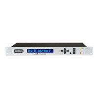
Alphanumeric Display/Keypad:
Display: Brilliant 16x280 graphical dot-matrix vacuum-fluorescent.
Keypad: Enter, Back, Edit, Right, Left, Up, Down, Help.
System Status LEDs:
Sync LED: Amber LED pulses to indicate CDMA acquisition and lock status.
Alarm LED: Red LED indicates a fault condition.
Serial Port I/O:
Signal: I/O port at RS-232 levels for secure, local terminal access.
Parameters: 19200 baud, 8 data bits, no parity, 1 stop bit.
Connector: Rear-panel DB-9M connector labeled “RS-232”.
To connect to a computer, a null-modem adapter must be used. The serial cable provided with the
shipment is wired as a null-modem. Pinout for the RS-232 console port is shown below.
Note: For operational details see Chapter 9 - Console Port Control and Status.