S o n o m a U s e r M a n u a l
6
C H A P T E R T W O
7
S o n o m a U s e r M a n u a l
B A S I C I N S T A L L A T I O N
Sonoma Physical
Description
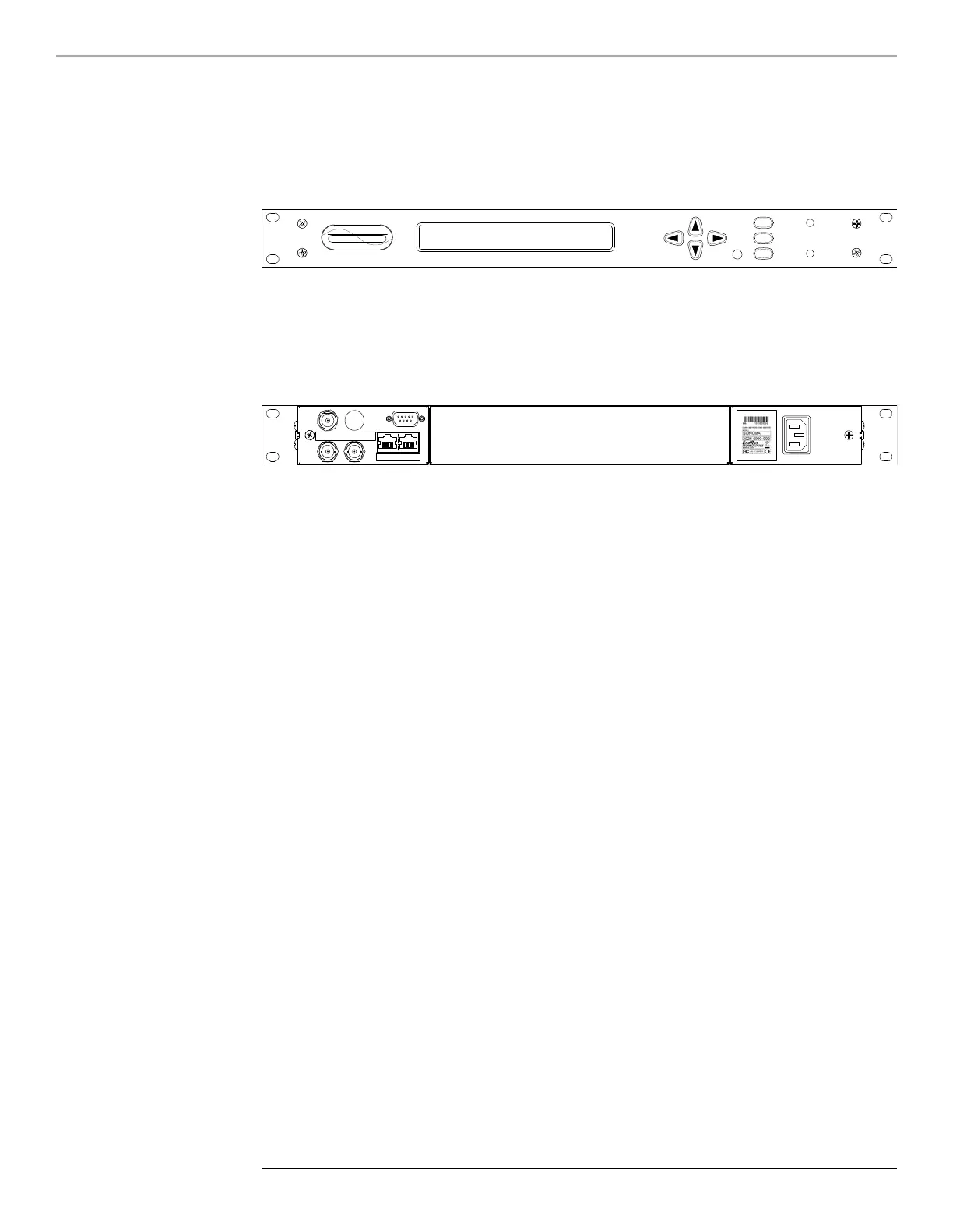
Sync LED This amber LED ashes to indicate synchronization status.
Alarm LED This red LED illuminates briey at power-up, and thereafter whenever
a serious fault condition exists.
The drawing above shows the Sonoma rear-panel in its most common conguration - with no op-
tional outputs. However, there are a wide variety of optional outputs available. For more informa-
tion see Chapter 10 - Options. (For a dimensional drawing of the Sonoma chassis see Appendix H
- Specifications.) Descriptions below briey describe the standard I/O connectors:
Antenna Jack This TNC connector mates with the downlead cable from the external
antenna.
RS-232 Connector This DB9M connector provides the RS-232 serial I/O console
interface to the Sonoma. This console allows you to initialize
and maintain the Sonoma. See Chapter 9 - Console Port Control
and Status for more information including the RS-232 pin assignments.
10/100/1000Base-T Jacks These two RJ-45 connectors mate with the Ethernet twisted pair cable
from the network. They are labeled with the corresponding MAC
address and either “ETH0” or “ETH1”. Integrated LEDs indicate link
speed (green) and activity (amber). The green LED will pulse once for
a speed of 10M, twice for 100M, and three times for 1G. Both ports
provide a console interface to the Sonoma. See Chapter 9 - Console
Port Control and Status for more information.
Spare Jacks These BNC connectors are usually labeled “SPARE”. When used,
they will be labeled with their connector identier (A, B, or C) and
provide optional signals. Label examples are: “A-AMCODE”,
“B-1PPS”, or “C-PPO”. For more information on Sonoma
options see Chapter 10 - Options.
AC Power Input Jack This IEC 320 standard three-prong connector provides AC power.
Other power supplies are available. See Chapter 10 - Options for
more information.