Enterasys 800-Series Hardware Installation Guide 3-1
3
Troubleshooting
This chapter contains instructions on troubleshooting the 800-Series as required. This can include:
Checking the LEDs
The following sections define the behavior of the LEDs on the 800-Series chassis models. The LEDs
on all chassis are located in the same location on the front panel.
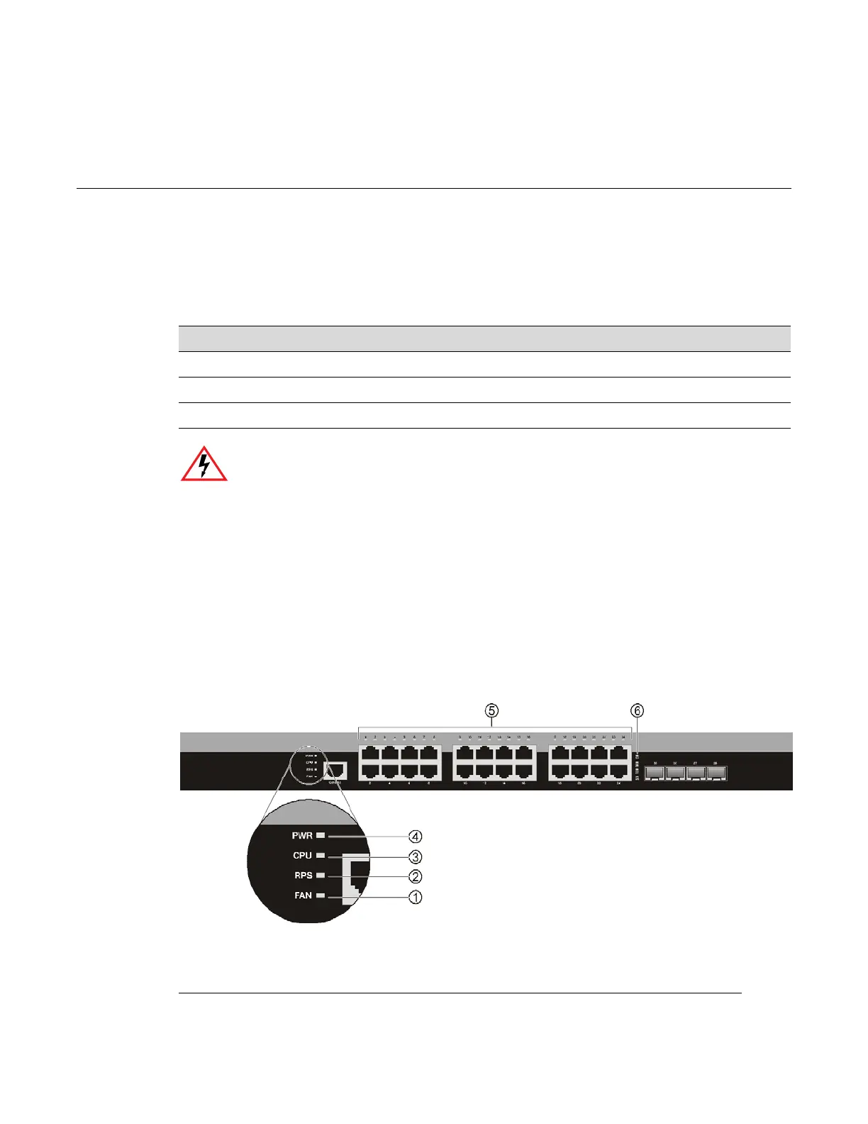
Refer to Figure 3-1 for the location of the LEDs on the chassis.
Figure 3-1 Switch status LEDs (08G20G4-24 shown)
For information about... Refer to page...
Checking the LEDs 3-1
Troubleshooting Checklist 3-6
Removing the Switch from a Rack 3-7
Electrical Hazard: Only qualified personnel should install or service this unit.
Riesgo Eléctrico: Nada mas personal capacitado debe de instalar o darle servicio a esta unida.
Elektrischer Gefahrenhinweis: Installationen oder Servicearbeiten sollten nur durch
ausgebildetes und qualifiziertes Personal vorgenommen werden.
1 Fan LED 4 Power (PWR) LED
2 Redundant Power Supply (PWR) LED 5 Copper 10/100/1000 Mbps port status LEDs
3 CPU LED 6 SFP 100/1000 Mbps port status LEDs
 Loading...


