Do you have a question about the Entrematic Ditec NeoS and is the answer not in the manual?
Safety guidelines for qualified personnel during installation and handling of components.
Ensuring safe installation environment, structural integrity, and proper use of safety devices.
Precautions for users to avoid hazards, ensure proper operation, and supervise children.
Specific precautions regarding children's interaction with the automated gate.
Rules for motor idle operation, avoiding operating range, and equipment disposal.
Manufacturer's declaration of conformity with relevant directives and standards.
Details installer's duties regarding technical data sheets, EC declarations, and affixing EC marking.
Technical details for NES300 and NES400 series including power, fuse, speed, and protection.
Technical details for NES600 series including power, fuse, speed, and protection.
Technical details for NES1000 series including power, fuse, speed, and protection.
Explanation of service class, applications, performance characteristics, and influencing factors.
Identifies standard installation components and provides guidelines for power supply and wiring.
Focuses on power supply connection via switch and separating mains from low voltage wiring.
Provides overall physical dimensions for the Ditec NeoS/NeoS+ gate automation.
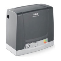
Illustrates and lists the primary components of the gate automation system for identification.
General recommendations regarding DITEC accessories and measurement units.
Ensures stability of the wing, wheels, guides, and proper fitting of stops/safety edges.
Instruction to install safety devices at the wing's end to mitigate collision force.
Steps for inserting anchor ties, securing screws, and preparing the concrete base for the plate.
Guidance on using M8 plugs for fixing the base plate to an already prepared concrete base.
Instructions for releasing, positioning, and adjusting the gearmotor on the base plate.
Details on fixing the gearmotor and a warning about raising it to prevent flooding.
Procedure for placing and fixing the rack along the gate, aligning it with the pinion.
Guide to adjust gearmotor for correct pinion-rack play and apply lubrication.
Explains NEOS gearmotors use virtual encoders and automatic slowdown at end stops.
Instructions for installing limit switch brackets on the rack for precise gate stopping.
Adjusting limit switches to ensure the gate stops approximately 20mm before mechanical stops.
Detailed steps for removing pinion, fixing plate, inserting pinions, and passing chain.
Instructions for attaching chain brackets to the gate and connecting the chain to the tie rod.
Important note to install the chain drive kit before securing the gearmotor to the base plate.
Ensuring correct distance between pinion and tie rod, securing chain with nuts.
Warning that the chain traction kit installation inverts the gearmotor drive direction.
Explanation of 'LF' for Right-hand opening and 'RT' for Left-hand opening.
Refers to CS12E/CS12M manuals for gearmotor wiring and start-up procedures.
Connecting the power supply with an omnipolar switch and ensuring system protection.
Guidelines for cable type, section, unsheathing, fasteners, and separating power/low voltage wires.
Installing photocells, compliance with standards, and connecting safety contacts.
Key safety warnings and guidelines for users to ensure safe operation of the automated gate.
Instructions on using the key to manually release and open/close the gate when the motor is idle.
Warning that the release microswitch prevents maneuvers when the hatch is closed.
Instructions for performing safety checks every 6 months and advice on repairs by qualified personnel.
Details on installing and checking safety devices like photocells, safety edges, and radio systems.
Lists common issues like no power, short-circuits, friction, and their possible causes.
Explains LED signals for power status, normal operation, alarms, and release door status.
Emphasizes using original spare parts and providing users with operation information.
Installer must keep a maintenance record showing all routine and extraordinary work performed.
| Type | Sliding gate opener |
|---|---|
| Power Supply | 230V AC |
| Motor Voltage | 24V DC |
| Operating Temperature | -20°C to +55°C |
| Max Gate Weight | 600 kg |
| Motor Type | DC |
| Safety Features | Obstacle detection |
| Control Options | Remote control, push button |