Initial Installation
QUALIFIED INSTALLERS ONLY
venting cLeaRances:
A 1” (25 mm) clearance to combustibles must be maintained around any vertical vent pipe. Around a
horizontal vent pipe, the clearance to combustibles should be 2” (51 mm) above and 1½” (38 mm) on the
sides and bottom. When combustible materials are directly above a 90° elbow, 3” (76 mm) of clearance
are necessary.
Table 2. Vent Pipe Minimum Clearances.
Vertical Pipe to
the Side Walls
Horizontal Pipe to
the Sides & Bottom
Above an Elbow
Above the Unit
Above an Elbow
Not Above the Unit
Above Horizontal
Vent Pipe
Wall Frame 8”
(203mm) or less
Hard
Pipe
1”
(25.4 mm)
1½”
(38.1 mm)
3”
(76.2 mm)
3”
(76.2 mm)
2”
(51 mm)
10”x10”
(25x25cm)
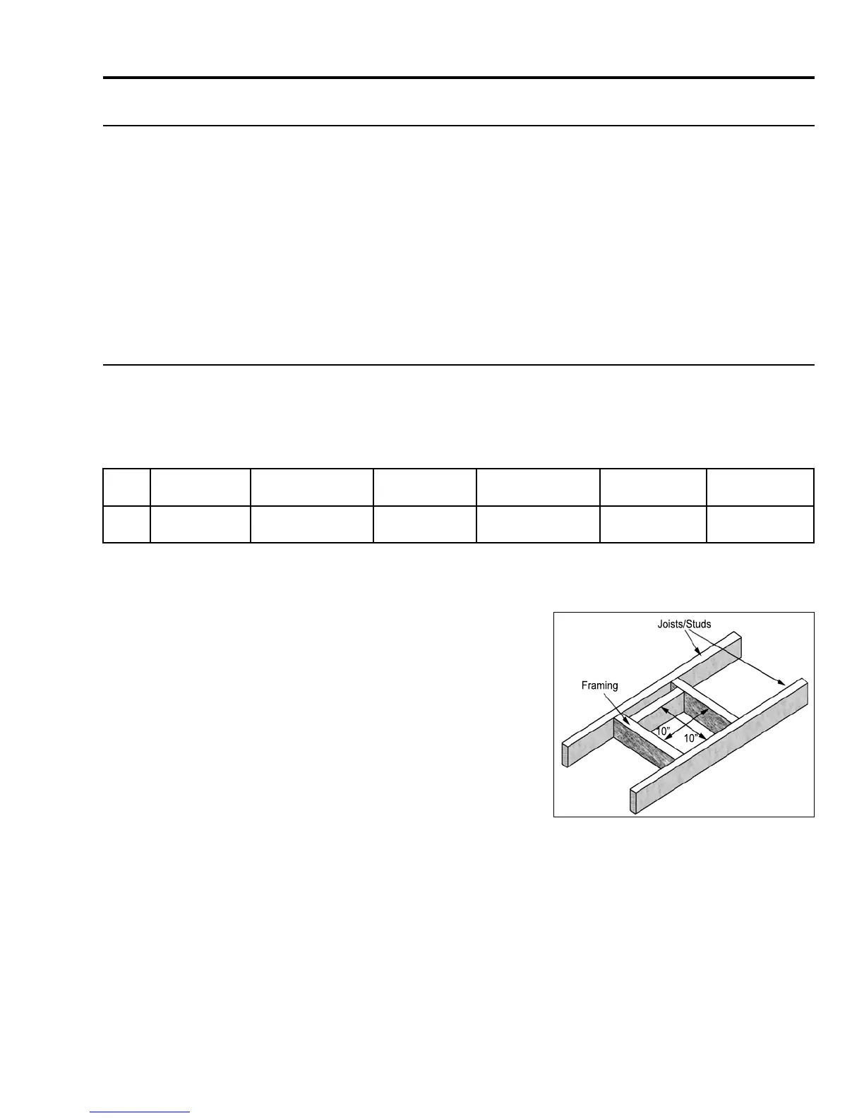
A 10” (254 mm) x 10” (254 mm) frame (see Figure 31) will assure the proper support and spacing for
the vent pipe as it passes through the wall. Installations in Canada require that a wall thimble be used for
passing through walls and ceilings. All sealing and vapour barriers must comply with local building codes.
Framing
Joists/Studs
10”
10”
The conguration of the venting pipes depends on the locations
of walls, ceilings, and studs. However, the pipes cannot be of
arbitrary length and arrangement. Because the length of the
vertical and horizontal sections dramatically affects the burning
efciency of the replace, certain guidelines have been set in
InItIal InstallatIon - allowaBle Vent confIguratIons. Venting
terminals can not be recessed into a wall or siding.
WARNING: This gas appliance must not be connected
to a chimney ue serving a separate solid-burning
appliances.
Figure 31. Vent Framing For Wall or Ceiling.
DiRect vent:
WARNING: This appliance has been designed to draw room air for proper heat circulation
from the bottom of the unit, and out the top front. Blocking or modifying these openings in
any way can create hazardous situations.
The vent length for the Berkeley must be between 36” (91 cm) and 44ft (13.4 m). This model is vented
with co-axial 4” intake, 6 5/8” exhaust aluminum or stainless steel approved rigid vent leading into a vertical
or horizontal termination cap. The ue collar of this model will t inside of a standard 4” x 6 5/8” vent and
must be either correctly interlocked or fastened, with three screws directly to the vent.
Check periodically that the vents are unrestricted. Also ensure that all direct vent pipes have been properly
sealed and installed after routine inspection or cleaning. The air intake and exhaust pipes must be installed
in the correct location on top of the Berkeley.
21