Technical Manual 5050 / MAN000539 Page 25/92
Epec Oy reserves all rights for improvements without prior notice
Epec Oy Postiosoite/Postal address Puhelin/Phone Fax Internet
Tiedekatu 6 PL/P.O.Box 194 +358-(0)20-7608 111 +358-(0)20-7608 110 www.epec.fi
FIN-60320 Seinäjoki FIN-60101 Seinäjoki, Finland
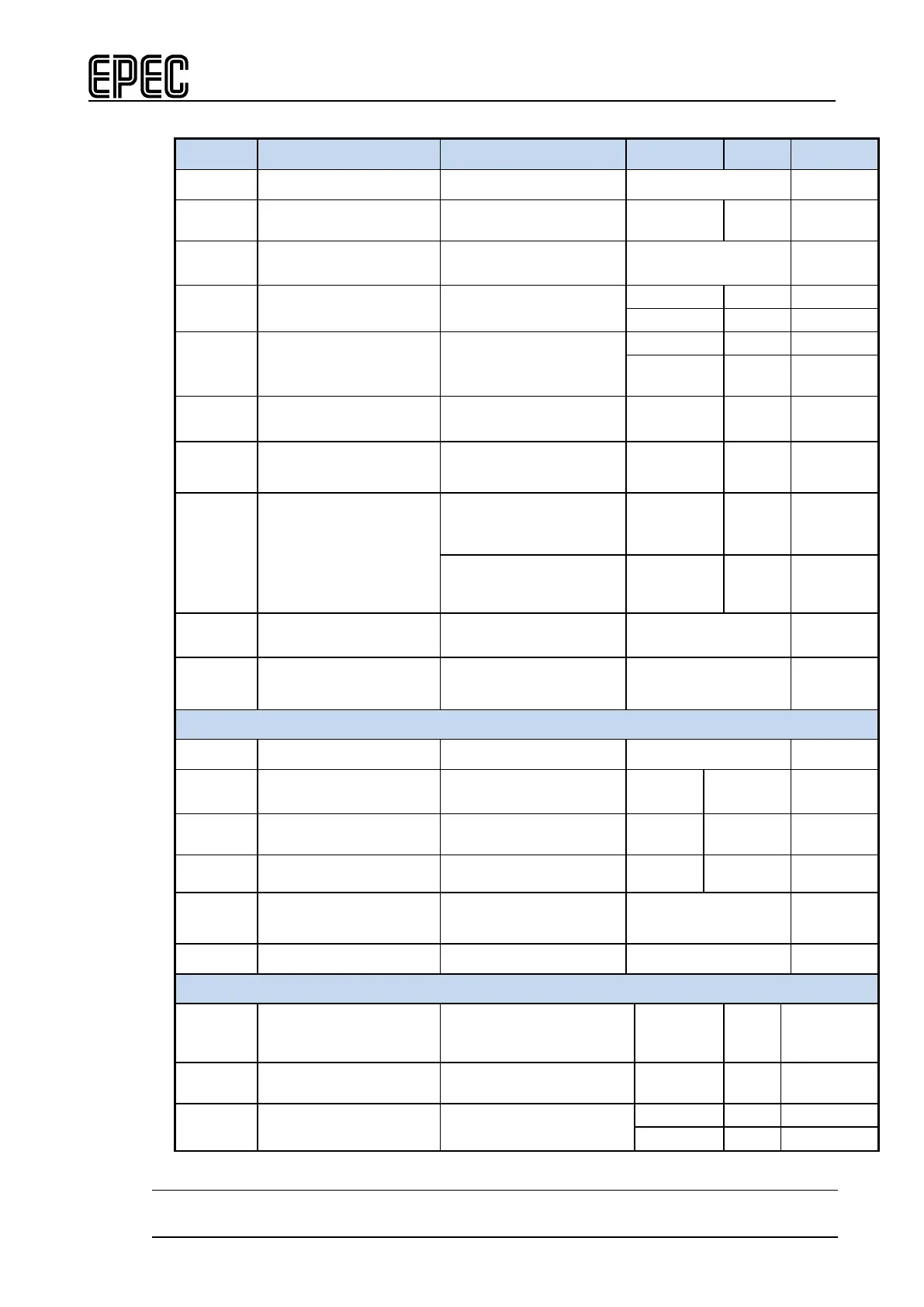
Electrical characteristics
Symbol Parameter Conditions Min Max
Units
R
Shunt
Shunt resistance
typ. 68 mΩ
I
o-range
Nominal Current
0 3,5 A
f
Cut-Off
Cut-off frequency
Output current
measuring
typ. 50 Hz
Iacc-zero
Offset error Calculated 'worst case'
I
acc-prop
Accuracy
Proportional factor
Calculated 'worst case'
+/-
mA (FS)
I
o
Nominal Output Current
Output On
(Note 6, 8)
0 2,5 A
I
o-lim
Internal current limitation
Output On
(Note 7)
2,5 A
f
PWM
PWM Frequency
In current measurement
mode
50 200 Hz
In PWM mode
(Note 1)
10 3000 Hz
Duty
PWM
PWM
Duty cycle
(Note 2, 9)
0 to 100 %
Res
PWM
PWM Resolution (Note 3) 0,1 %
Digital status input
R
I
Input Resistance
Output Off
Typ. 12 kΩ
V
IH
Digital status input
High Voltage level
Output Off (Note 5)
3,2 V
V
IL
Digital status input
Output Off
1,9 V
V
I-range
Input voltage range (Note 12) -0,5 U
in
+ 0,2V
V
t
I
Digital Status Input
Pulse Width
(Note 2, 4, 11)
> tC ms
C
I
Input pin capacitance
typ. 1
nF
Output/input voltage monitoring
V
0-range
Nominal Output/input
Voltage measuring
(Note 10) 0 55 V
V
I-prop
Measuring accuracy
Calculated
+/-1 %
V
I-zero
Offset Error Calculated